How Does a Spacecraft Thermal Control System Work?

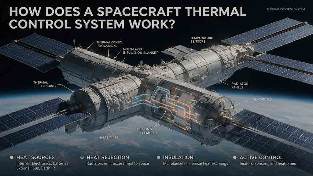
How Does a Spacecraft Thermal Control System Work?
A spacecraft thermal control system keeps hardware within its operating and survival temperature limits by controlling how heat is absorbed, generated, transported, stored, and rejected. Passive features such as insulation, coatings, radiators, thermal straps, and heat pipes establish the main heat paths. Sensors, heaters, cryocoolers, and fluid loops provide active control when a mission needs tighter temperature stability or greater heat-moving capacity.
Key Takeaways
- Spacecraft can overheat in sunlight even though space is cold because external vacuum provides almost no convective cooling.
- Excess heat must follow a designed path from the source to a radiator, which releases energy as infrared radiation.
- Multilayer insulation reduces radiative heat transfer; it does not create cold or eliminate heat.
- Passive thermal control minimizes power use and complexity, while active control supports tighter limits, larger loads, and changing operating conditions.
- A complete design must work during normal operation, eclipse, safe mode, contingencies, and expected end-of-life degradation.
This guide explains the full heat path inside a spacecraft, compares passive and active technologies, presents two transparent calculation examples, and shows how real missions solve different thermal problems.
Engineering scope: This article is an educational overview based on public engineering documentation and first-principles calculations. It is not a flight-design specification, certification basis, operating procedure, or substitute for mission-specific analysis, testing, safety review, and engineering approval.
How Does a Spacecraft Thermal Control System Manage Heat?
A practical way to understand a spacecraft thermal control system is through five connected jobs: Protect, Move, Reject, Trim, and Verify.
| Job | Question the design must answer | Typical methods |
|---|---|---|
| Protect | How is unwanted environmental heating or cooling limited? | Multilayer insulation, coatings, sunshields, orientation, isolation |
| Move | How does heat travel away from a component? | Mounting interfaces, conductive panels, straps, heat pipes, fluid loops |
| Reject | Where does excess heat leave the spacecraft? | Fixed or deployable radiators |
| Trim | How are temperatures corrected when passive control is insufficient? | Heaters, thermostats, cryocoolers, thermoelectric devices |
| Verify | How is performance demonstrated and monitored? | Models, sensors, thermal-balance tests, thermal-vacuum tests, telemetry |
This framework keeps the design focused on heat paths rather than hardware lists. A heat pipe without a suitable radiator, a heater without representative sensing, or a blanket without a defined thermal purpose may add mass without solving the temperature problem.
What Does the Thermal Energy Balance Mean?
A simplified conceptual energy balance for one thermal node can be written as:
$$
\dot{Q}{\text{solar}}
+
\dot{Q}{\text{albedo}}
+
\dot{Q}{\text{planet IR}}
+
\dot{Q}{\text{generated}}
+
\sum \dot{Q}_{\text{in}}
\dot{Q}_{\text{radiated}}
\sum \dot{Q}_{\text{out}}
C_{\text{th}}\frac{dT}{dt}
$$
Where:
- (\dot{Q}) represents a heat-transfer rate in watts;
- (C_{\text{th}}) is the thermal capacitance of the node in joules per kelvin;
- (T) is the node temperature;
- (dT/dt) describes how quickly that temperature changes.
In an approximate steady state, (dT/dt) approaches zero, so incoming and internally generated heat is balanced by outgoing heat. During eclipse entry, instrument startup, transmitter operation, or another transient event, the imbalance changes the node temperature.
A real spacecraft model contains many connected nodes rather than one overall spacecraft temperature. Each node may exchange energy through conduction, radiation, contact interfaces, fluid flow, and changing internal power.
NASA’s Small Spacecraft Technology State-of-the-Art thermal-control chapter presents a simplified spacecraft heat balance. Mission teams develop more detailed models for their actual geometry, materials, operating modes, and environments.
Why Is Thermal Control Different in Space?
Thermal control is different in space because the environment around a spacecraft is nearly a vacuum.
On Earth, warm hardware can transfer heat to surrounding air through natural or forced convection. Outside a spacecraft, that external convective path is essentially absent. Heat leaves exposed surfaces mainly through thermal radiation.
Inside the vehicle, heat can still move through solid structures, mechanical interfaces, heat pipes, circulating liquids, and—inside a pressurized cabin—moving air.
The Three Heat-Transfer Mechanisms
Conduction transfers energy through physical contact. Heat from an electronics unit may pass through its baseplate, mounting feet, interface material, structural panel, and thermal strap.
Convection transfers energy through a moving fluid. It does not provide useful cooling from an external spacecraft surface into vacuum, but it can operate inside a pressurized module or within a pumped coolant system.
Radiation transfers energy through electromagnetic waves. A radiator uses this mechanism to reject heat without requiring surrounding air.
The objective is therefore not simply to make the spacecraft colder. Engineers must create useful heat paths while limiting unwanted thermal coupling between components with different requirements.
What Heat Sources Affect a Spacecraft?
A spacecraft’s temperature depends on environmental heating, internal power dissipation, thermal storage, orientation, and radiative heat rejection.
Direct Solar Radiation
Sunlight may be the dominant external heat source for an exposed surface.
The absorbed power depends on:
- solar intensity;
- distance from the Sun;
- exposed area;
- incidence angle;
- shadowing;
- surface solar absorptivity.
A thermal design developed for Earth orbit cannot automatically be applied near Mercury, in the outer solar system, or during a mission that experiences widely changing solar distance.
Planetary Albedo
Albedo is sunlight reflected by a planet, moon, cloud layer, or surface.
An Earth-facing spacecraft panel can absorb reflected sunlight even when it does not point directly toward the Sun. The effect depends on the planetary surface, cloud conditions, orbit, attitude, optical properties, and the fraction of the planet visible to the panel.
Planetary Infrared Radiation
Planets and moons emit thermal infrared energy.
A spacecraft surface facing Earth, for example, may absorb planetary infrared energy in both sunlight and eclipse. The absorbed amount depends on the body’s apparent size, thermal environment, surface emissivity, geometry, and view factor.
Internal Waste Heat
Most electrical energy used by spacecraft equipment eventually becomes heat, but it may not appear at a single location.
A nominally 40-watt unit could distribute energy among:
- processors and internal electronics;
- power-conversion losses;
- harness losses;
- radio-frequency output;
- mechanical work;
- another external load.
Thermal engineers therefore follow the actual power path instead of assigning every watt of rated electrical power to one model node.
Common internal heat sources include:
- flight computers;
- radio transmitters and amplifiers;
- batteries;
- power converters;
- reaction wheels;
- scientific instruments;
- pumps and cryocoolers;
- heaters;
- mechanisms operating for short periods.
Is Deep Space Always an Ideal Cold Heat Sink?
No. “Viewing deep space” is useful shorthand, but a radiator rarely sees only the cosmic background.
The effective radiative sink may be much warmer because the radiator also views:
- Earth or another planetary body;
- the Sun;
- a warm spacecraft panel;
- a deployed antenna or solar array;
- reflected sunlight;
- planetary infrared radiation;
- structures that obstruct part of its field of view.
Engineers therefore evaluate environmental heat fluxes, solid-angle view factors, nearby surface temperatures, attitude, and obstruction. They do not assume that every outward-facing radiator sees an unobstructed background near 3 kelvins.
How Does Passive Thermal Control Work?
Passive thermal control regulates heat without continuously powered pumps or refrigeration machinery.
NASA’s Passive Thermal Control Engineering Guidebook, Revision 4.0 covers passive thermal design practices, coatings, insulation, interfaces, heat transport, heaters, analysis, testing, and model correlation.
Thermal Coatings and Surface Finishes
Thermal coatings influence how strongly a surface absorbs sunlight and emits infrared energy.
Two properties are especially important:
- Solar absorptivity, (\alpha): the fraction of incoming solar energy absorbed by the surface;
- Infrared emissivity, (\varepsilon): the surface’s effectiveness at emitting thermal radiation.
A Sun-facing surface may benefit from low solar absorptivity. A radiator generally benefits from high infrared emissivity. The appropriate combination depends on orientation, operating temperature, nearby surfaces, contamination risk, and mission duration.
Visible color does not determine thermal performance by itself. Two materials that both appear white, black, gold, or metallic may have substantially different optical properties.
Those properties can also change through:
- ultraviolet exposure;
- atomic oxygen in low Earth orbit;
- radiation;
- contamination;
- handling damage;
- repeated thermal cycling.
Thermal models may therefore use different beginning-of-life and end-of-life optical properties.
Multilayer Insulation
Multilayer insulation, or MLI, consists of several thin reflective layers separated by low-conductance spacers.
MLI reduces radiative exchange between the spacecraft and its surroundings. It can limit environmental heating and prevent warm internal hardware from losing heat too quickly.
The familiar gold- or silver-colored blanket is not conventional thick insulation. Its effectiveness depends on the complete installed system, including:
- the number and spacing of layers;
- outer-cover properties;
- compression;
- seams and edges;
- fasteners;
- cable and pipe penetrations;
- venting;
- accidental contact with nearby surfaces.
Compression or poor installation can create conductive shortcuts that significantly reduce performance.
ESA provides a concise overview of multilayer insulation, radiators, heaters, and spacecraft thermal distribution.
Radiators
A radiator is a surface designed to emit unwanted energy as infrared radiation.
It is the final part of a heat path, not a standalone cooling device. Heat must first reach the radiator through a conductive structure, strap, heat pipe, cold plate, or fluid loop.
Radiator performance depends on:
- effective emitting area;
- infrared emissivity;
- surface temperature;
- orientation;
- view of planets and nearby structures;
- absorbed environmental energy;
- coating degradation;
- temperature losses between the source and radiator.
A radiator is not necessarily the coldest part of the spacecraft. It is the surface intentionally configured to provide predictable heat rejection.
Thermal Straps
A thermal strap is a flexible conductive connection between a heat source and another thermal node.
Common materials include copper, aluminum, graphite sheets, and graphite fibers. Flexibility allows the strap to accommodate vibration, alignment, deployment, and differential thermal expansion more easily than a rigid metal bar.
Actual conductance depends on more than the bulk material. Important details include:
- length;
- cross-sectional area;
- bends;
- clamping;
- contact pressure;
- end-block design;
- interface materials.
A high-conductivity strap can still perform poorly if either attachment interface has high thermal resistance.
Heat Pipes
A heat pipe is a sealed device that transports energy through evaporation, vapor flow, condensation, and liquid return.
At the warm end, a working fluid evaporates. The vapor moves toward the cooler end, condenses, and releases heat. A wick or another capillary structure returns the liquid toward the evaporator.
Spacecraft heat-pipe performance depends on:
- operating-temperature range;
- capillary limits;
- geometry;
- working-fluid inventory;
- startup conditions;
- heat input;
- condenser conditions.
A conventional capillary heat pipe does not depend on a permanent terrestrial “up” direction in microgravity. Gravity orientation can matter during ground testing, launch-site handling, or planetary-surface operation.
Related devices include loop heat pipes, variable-conductance heat pipes, diode heat pipes, and flat heat pipes.
Thermal Isolation
Some components should be only weakly connected to the surrounding structure.
Low-conductivity mounts, reduced contact areas, isolating washers, controlled harness routing, and specialized supports can limit unwanted heat transfer.
Isolation is useful for:
- precision optical instruments;
- cryogenic detectors;
- batteries requiring a warmer environment;
- mechanisms with narrow operating limits;
- payloads that must remain thermally independent from the spacecraft bus.
Isolation is never perfect. Fasteners, harnesses, pipes, optical supports, and structural members can all become parasitic heat paths.
Thermal Mass and Phase-Change Storage
Thermal mass slows temperature changes by storing energy.
It can help a component tolerate a short eclipse or brief high-power event, but stored energy must eventually be rejected. Additional thermal mass also increases spacecraft mass.
Phase-change materials store energy while changing phase within a selected temperature range. They can reduce short-duration temperature peaks, but they require suitable containment, interfaces, cycling behavior, and a later path for releasing the stored energy.
How Does Active Thermal Control Work?
Active thermal control uses electrical power, feedback, moving fluid, or refrigeration hardware to control temperature or transport heat.
It is used when passive hardware cannot provide the required stability, temperature range, heat-transport distance, or heat-rejection capacity.
Electrical Heaters
Resistance heaters convert electrical energy into heat.
They are commonly used on:
- batteries;
- propulsion lines and tanks;
- valves;
- mechanisms;
- instruments;
- optical benches;
- intermittently operated electronics.
A heater may be controlled by a thermostat, redundant thermostats, flight software, or a dedicated controller.
Heater location, sensor location, control thresholds, power density, thermal contact, and fault behavior all affect performance. Heater demand must also be included in the power budget because the coldest conditions may occur during eclipse, when solar-array power is unavailable.
Temperature Sensors and Controllers
Temperature sensors provide the measurements used to operate and assess the thermal-control system.
Common sensor types include:
- thermistors;
- resistance temperature detectors;
- thermocouples;
- semiconductor temperature sensors.
Sensor placement is often more important than sensor type.
A sensor attached to an equipment chassis may not represent:
- an internal semiconductor junction;
- the center of a battery cell;
- a detector;
- a mechanism bearing;
- a fluid-line cold spot;
- a poorly conducting mounting interface.
The measured location must either represent the actual risk temperature or have a defensible analytical and test correlation to it.
Pumped Fluid Loops
A pumped fluid loop collects heat, moves it through tubing, and transfers it to a heat exchanger or radiator.
A typical loop can include:
- pumps;
- tubing;
- cold plates;
- heat exchangers;
- valves;
- accumulators;
- flow, pressure, and temperature sensors;
- redundant flow paths;
- radiators.
Pumped loops are useful when heat loads are large, widely distributed, variable, or far from the available radiator.
Their disadvantages include additional mass, electrical demand, plumbing, control logic, moving components, leak risk, and integration complexity.
Cryocoolers
A cryocooler is a powered refrigeration system used when passive cooling cannot achieve the required temperature.
Cryocoolers may support infrared detectors and other low-temperature instruments. They also introduce:
- electrical demand;
- vibration;
- mechanical interfaces;
- control requirements;
- additional warm-side waste heat.
A cryocooler does not make heat disappear. Its rejection system must remove both the heat extracted from the cold instrument and most of the cryocooler’s electrical input.
Thermoelectric Coolers
A thermoelectric cooler moves heat across a solid-state junction when electrical current is applied.
It can provide compact local control without a circulating fluid, but its hot side must reject the heat removed from the cold side plus the electrical power consumed by the device.
Its efficiency generally decreases as the required temperature difference and heat load increase.
Which Is Better: Passive or Active Thermal Control?
Neither strategy is universally better.
| Design question | Passive approach | Active approach |
|---|---|---|
| Operating power | Usually little or none | Requires electrical power |
| Best temperature range | Broad or predictable limits | Tight, changing, or very low limits |
| Heat-transport capability | Effective when conductive paths and radiator area are sufficient | Better for large, distributed, or distant loads |
| Added system burden | Materials, area, and mechanical integration | Controls, power, sensors, pumps, or refrigeration hardware |
| Typical role | Establishes the baseline thermal environment | Handles conditions passive control cannot efficiently cover |
Most spacecraft combine both approaches. Passive hardware defines the basic heat balance, while heaters or other active devices manage eclipses, changing operating modes, cold survival, high-power equipment, or specialized instruments.
The following table compares individual hardware choices within those strategies.
| Hardware | Primary advantage | Important limitation |
|---|---|---|
| Coating or finish | Low mass and no operating power | Optical properties can degrade or become contaminated |
| MLI | Strong reduction of radiative exchange | Installation quality strongly affects performance |
| Thermal strap | Flexible conductive path | Geometry and end interfaces limit conductance |
| Heat pipe | High effective conductance without a mechanical pump | Capillary, startup, temperature, and condenser limits apply |
| Radiator | Direct heat rejection | Requires area and a suitable radiative field of view |
| Heater | Simple local cold protection | Consumes limited spacecraft power |
| Pumped loop | Handles large or distributed loads | Adds plumbing, controls, mass, power, and leak risk |
| Cryocooler | Enables very low temperatures | Adds power, vibration, complexity, and warm-side heat |
How Does Heat Move Through a Spacecraft Step by Step?
The five-job framework describes what the system must accomplish. The following sequence shows how those jobs appear during spacecraft operation.
Step 1: The Mission Creates a Thermal Condition
Sunlight, albedo, planetary infrared energy, eclipse, attitude, internal power, and operating modes establish the current thermal environment.
A transmitter activation may create a concentrated internal load. Entering eclipse may remove solar heating. A science observation can change both attitude and instrument dissipation.
Step 2: Exterior Features Limit Unwanted Heat — Protect
Coatings, MLI, sunshields, geometry, and attitude reduce unwanted heating or heat loss.
One surface may be intentionally exposed to sunlight while an instrument is shaded and a radiator remains pointed away from the Sun.
Step 3: Designed Interfaces Carry Heat Away — Move
Heat crosses mounting surfaces and then travels through structural panels, straps, heat pipes, cold plates, or fluid loops.
Each interface adds thermal resistance. A poor mounting contact can dominate the complete path even when the downstream strap or radiator is capable.
Step 4: A Radiator Releases Heat — Reject
The transported heat raises the radiator temperature until the radiator emits energy to its surroundings.
A radiator facing Earth or a warm spacecraft surface rejects less net heat than the same radiator with a clearer, colder field of view.
Step 5: Active Devices Correct the Remaining Error — Trim
If a component becomes too cold, a heater adds energy. If a detector must operate below its passive equilibrium temperature, a cryocooler moves heat to a warmer rejection system.
The objective is not to hold the entire spacecraft at one temperature. Each thermal zone is controlled according to its own requirements.
Step 6: Operations Change the Heat Balance
Mission operations can support thermal control by:
- limiting transmitter duty cycle;
- staggering high-power activities;
- changing attitude;
- delaying an operation;
- warming hardware before activation;
- reducing loads during safe mode;
- reserving battery energy for heaters.
Operational planning cannot repair an inadequate thermal design, but it can prevent incompatible loads from occurring together.
Step 7: Telemetry Confirms Performance — Verify
Temperature measurements, heater currents, pump states, valve positions, power modes, and spacecraft attitude are transmitted to the ground.
Engineers compare the trends with model predictions. A gradual temperature shift may indicate:
- changed power dissipation;
- sensor drift;
- altered thermal contact;
- coating degradation;
- blanket damage;
- contamination;
- an unmodeled operating condition.
How Do Engineers Select a Thermal Architecture?
Engineers begin with mission requirements and heat paths, not with a preferred product or device.
1. Define Temperature Requirements
Each critical component should have:
- an operating temperature range;
- a non-operating survival range;
- allowable gradients;
- stability requirements;
- permissible rates of temperature change;
- warm-up or cooldown limits where relevant.
A component may survive a broad temperature range but still require much tighter stability while performing its function.
2. Define Mission Phases
Relevant thermal cases can include:
- launch;
- deployment;
- early orbit;
- transfer or cruise;
- eclipse;
- science operations;
- communication passes;
- propulsion events;
- safe mode;
- contingency attitudes;
- end-of-life operation.
The most severe hot or cold condition may occur outside the normal mission mode.
3. Map Internal Power Dissipation
Power must be allocated by operating mode and by where it actually becomes heat.
Engineers distinguish among:
- rated power;
- average power;
- peak power;
- duty cycle;
- conversion losses;
- radio-frequency output;
- mechanical output;
- harness losses.
4. Reserve Radiator Area Early
Radiators compete with solar cells, antennas, optical apertures, sensors, thrusters, access panels, and deployment mechanisms for exterior area.
A radiator should be part of the early spacecraft configuration rather than assigned to whatever surface remains late in the design.
5. Create Thermal Zones
Components with compatible limits may share a structure or radiator. Components with conflicting needs may require isolation.
A warm battery, high-power transmitter, stable telescope, and cryogenic detector should not be modeled as one uniform spacecraft temperature.
6. Analyze Hot, Cold, and Transient Cases
A larger radiator may improve a hot case while making eclipse operation too cold. More insulation may improve cold survival while trapping excessive internal heat.
Every major thermal change should therefore be assessed against both hot and cold mission cases.
7. Include Uncertainty and Degradation
Thermal predictions depend on imperfectly known inputs, including:
- contact conductance;
- coating properties;
- contamination;
- internal power;
- sensor accuracy;
- workmanship;
- view factors;
- orbital environment;
- material aging.
Flight programs apply mission-specific uncertainty and margin policies rather than treating nominal predictions as exact.
Mission-to-Architecture Selection Table
| Mission condition | Practical starting architecture | Primary reason |
|---|---|---|
| Low-power spacecraft with broad limits | Coatings, conductive structure, small radiator, limited heaters | Low mass and power demand |
| Frequent eclipses | MLI, thermal mass, thermostatic heaters | Limits cold excursions |
| Concentrated high-power electronics | Strong mounting path, strap or heat pipe, dedicated radiator | Reduces local hot spots |
| Loads far from radiator area | Loop heat pipe or pumped fluid loop | Long-distance heat transport |
| Precision optical payload | Isolation, stable radiator, distributed sensing, controlled heaters | Reduces gradients and drift |
| Cryogenic detector | Sunshield, isolation, staged radiators, cryocooler if required | Enables very low temperature |
| Large crewed vehicle | Air and liquid loops, heat exchangers, large radiators, redundancy | Handles distributed changing loads |
| CubeSat or nanosatellite | Structure, coatings, compact straps, selected heaters | Severe area, volume, mass, and power limits |
| Outer-solar-system probe | Strong insulation, heat reuse, carefully budgeted heaters | Weak solar input and limited electrical power |
NASA’s 2024 small-spacecraft technology review, published as NASA/TP—20250000142 in 2025, identifies low thermal mass, limited exterior area, limited internal volume, constrained power, high power density, and MLI edge effects as important SmallSat thermal challenges.
The One-Path Thermal Audit
The One-Path Thermal Audit is an explanatory framework created for this guide. It is not a NASA, ESA, or industry standard.
For each heat-producing or temperature-sensitive component, answer six questions:
- How much heat does the component generate in each mode?
- What operating and survival temperatures must it remain within?
- Through which physical interface does heat first leave or enter?
- Where is the final radiator, heater, storage element, or heat sink?
- What changes during eclipse, safe mode, or shutdown?
- Which sensor represents the temperature that creates the real risk?
A thermal path is incomplete if the answer stops at “the heat enters the spacecraft structure” without identifying its final destination.
Example: Following a 40-Watt Power Amplifier
Consider an illustrative radio-frequency amplifier that dissipates 40 watts as local heat during a communication pass.
Assume these simplified thermal resistances:
- baseplate and mounting interface: (0.12\ \text{K/W});
- structural panel and heat pipe: (0.08\ \text{K/W});
- condenser-to-radiator interface: (0.05\ \text{K/W}).
The total assumed resistance is:
$$
R_{\theta,\text{total}}
0.12 + 0.08 + 0.05
0.25\ \text{K/W}
$$
The estimated temperature difference between the amplifier baseplate and radiator is:
$$
\Delta T
\dot{Q}R_{\theta,\text{total}}
$$
$$
\Delta T
40\ \text{W}
\times
0.25\ \text{K/W}
10\ \text{K}
$$
If the radiator surface is at 300 K under this simplified condition, the estimated amplifier baseplate temperature is approximately:
$$
T_{\text{baseplate}}
300\ \text{K}
+
10\ \text{K}
310\ \text{K}
$$
This is an illustrative calculation, not flight data. A real model would also consider:
- internal amplifier junction temperatures;
- time-varying operation;
- temperature-dependent conductance;
- interface uncertainty;
- harness heat paths;
- nearby thermal nodes;
- radiator environmental loading;
- nonuniform radiator temperature.
The lesson is practical: a capable radiator cannot protect the amplifier if a high-resistance mounting interface prevents heat from reaching it.
How Large Must a Spacecraft Radiator Be?
Radiator area depends on heat load, temperature, emissivity, environment, effective view factor, surface degradation, heat-transport losses, and design margin.
An idealized radiator can be approximated with the Stefan–Boltzmann relation:
$$
\dot{Q}_{\text{rad}}
\varepsilon \sigma A
\left(
T_{\text{rad}}^4
T_{\text{sink}}^4
\right)
$$
Where:
- (\dot{Q}_{\text{rad}}) is net radiated power in watts;
- (\varepsilon) is infrared emissivity;
- (\sigma = 5.670 \times 10^{-8}\ \text{W/m}^2\text{K}^4);
- (A) is effective emitting area in square meters;
- (T_{\text{rad}}) is radiator surface temperature in kelvins;
- (T_{\text{sink}}) is the effective radiative sink temperature in kelvins.
Illustrative 120-Watt Radiator Calculation
Assume:
- heat to reject: (120\ \text{W});
- radiator surface temperature: (300\ \text{K});
- infrared emissivity: (0.85);
- one effective emitting surface;
- a sufficiently cold background that (T_{\text{sink}}^4) is neglected;
- no direct solar heating, albedo, planetary infrared load, or back-radiation.
First calculate ideal emitted power per unit area:
$$
\frac{\dot{Q}_{\text{rad}}}{A}
\varepsilon \sigma T_{\text{rad}}^4
$$
$$
\frac{\dot{Q}_{\text{rad}}}{A}
0.85
\times
5.670 \times 10^{-8}
\times
(300)^4
$$
$$
\frac{\dot{Q}_{\text{rad}}}{A}
\approx
390\ \text{W/m}^2
$$
The unit check is:
$$
\frac{\text{W}}
{\text{W/m}^2}
\text{m}^2
$$
The required effective area is:
$$
A
\frac{120\ \text{W}}
{390\ \text{W/m}^2}
\approx
0.31\ \text{m}^2
$$
What Does the 0.31-Square-Meter Result Mean?
The result represents approximately 0.31 square meters of effective radiating area, not necessarily 0.31 square meters of physical panel outline.
The example assumes that:
- the surface radiates mainly toward a cold background;
- 300 K is the radiator surface temperature, not the electronics temperature;
- there is no temperature drop between the equipment and radiator;
- the radiator absorbs no environmental heat;
- emissivity remains at the assumed value;
- contamination, degradation, installation variation, uncertainty, and design margin are excluded.
A flight radiator may require more area. Its physical outline may also differ from its effective radiating area because of obstruction, attachments, plumbing, edge effects, nonuniform temperature, or two-sided radiation.
The fourth-power relationship creates an important tradeoff: a warmer radiator rejects more heat per unit area, but the connected equipment must tolerate the higher temperature.
How Do Different Missions Solve Thermal Control?
There is no universal thermal-control architecture.
| Mission type | Dominant challenge | Common approach |
|---|---|---|
| CubeSat in low Earth orbit | Fast orbital cycling and limited radiator area | Coatings, conductive frame, compact straps, selected heaters |
| Earth-observation satellite | Repeated eclipse and instrument stability | MLI, heat pipes, dedicated radiators, controlled heaters |
| Communications spacecraft | High transmitter dissipation | Equipment placement, heat pipes, radiator panels, duty-cycle planning |
| Outer-solar-system probe | Weak sunlight and constrained electrical power | Insulation, heat redistribution, carefully budgeted heaters |
| Infrared observatory | Very low detector temperature | Sunshield, isolation, staged passive radiators, cryocooler |
| Crewed spacecraft or station | Large, distributed, changing loads | Cabin cooling, fluid loops, heat exchangers, external radiators |
| Lunar surface vehicle | Long illumination cycles and local extremes | Insulation, heaters, thermal storage, radiators, scheduling |
Why Are Small Spacecraft Not Automatically Easier to Cool?
Small spacecraft usually produce less total heat than large vehicles, but they also have:
- less thermal mass;
- less exterior radiator area;
- less internal volume;
- less power for active thermal control;
- tightly packed electronics;
- fewer options for isolating thermal zones.
Their temperatures can therefore change quickly, and a modest total heat load can create a severe local hot spot when there is no direct path to a radiator.
James Webb Space Telescope: Prevent Heat Before Removing It
The James Webb Space Telescope uses a five-layer sunshield to separate its warm spacecraft side from the telescope and instruments.
The layers are separated so that absorbed heat can radiate sideways rather than passing directly through a solid stack. The sunshield protects the observatory from thermal radiation associated with the Sun, Earth, and Moon.
Webb’s near-infrared instruments are cooled mainly through passive thermal design. Its Mid-Infrared Instrument requires a cryocooler to reach an operating temperature below 7 K, as described in NASA’s report on MIRI reaching its operating temperature.
The broader lesson is that preventing heat from reaching a sensitive instrument can be more efficient than absorbing that heat and trying to remove it later.
International Space Station: Collect, Transport, and Reject
The International Space Station produces large, distributed, and changing heat loads.
A NASA-hosted Boeing technical document, Active Thermal Control System Overview, describes three basic functions:
- heat collection;
- heat transportation;
- heat rejection.
Internal water loops collect heat from equipment in pressurized modules. Interface heat exchangers transfer that energy to external ammonia loops. The ammonia carries heat to radiators, which reject it to space.
The ISS architecture demonstrates why large crewed vehicles may require multiple loops, different working fluids, pumps, valves, heat exchangers, sensors, radiator assemblies, and fault-tolerant operating modes.
Europa Clipper: Reuse Waste Heat Before Rejecting It
Europa Clipper operates far from the Sun, where retaining useful heat can reduce heater demand. Its instruments and electronics can also generate substantial internal loads during operation.
NASA describes a Heat Redistribution System that pumps coolant through tubing around the spacecraft to help control temperature.
This example illustrates an often-overlooked principle: waste heat is not always only a disposal problem. Heat can first be moved from warmer regions to colder regions before any excess is rejected.
Designing Only for Normal Operation
Normal science operation may not produce the most severe thermal case.
Deployment delays, safe mode, attitude loss, long communication sessions, reduced power, failed heaters, and unusual eclipse exposure may create more demanding conditions.
Better practice: Analyze nominal, survival, contingency, beginning-of-life, and end-of-life cases.
Checking the Hot Case but Not the Cold Case
Increasing radiator area may solve overheating while creating an unacceptable eclipse or safe-mode cold case.
Better practice: Recheck cold conditions after changing radiator area, insulation, emissivity, conductance, or operating modes.
Assuming Perfect Contact Conductance
Real interfaces contain surface roughness, coatings, gaps, limited fastener pressure, interface materials, and assembly variation.
Better practice: Model contact conductance explicitly and verify critical interfaces with representative testing or correlated data.
Treating MLI as a Perfect Barrier
Seams, supports, fasteners, harnesses, vents, blanket edges, and penetrations transfer heat.
Better practice: Model the installed blanket and its parasitic paths rather than only the ideal layer material.
Placing a Sensor Where Installation Is Easy
A convenient sensor may not measure the actual hot spot or cold spot.
Better practice: Identify the temperature that controls performance or survival, then place or correlate the sensor accordingly.
Forgetting Active-System Waste Heat
Pumps, thermoelectric devices, and cryocoolers consume power that eventually becomes heat.
Better practice: Include transported heat, electrical input, and inefficiency in the downstream radiator load.
Treating the Structure as the Final Heat Sink
“The heat goes into the panel” is not a complete heat-path description.
Better practice: Trace the energy through the panel to a radiator, fluid loop, storage device, or another defined destination.
Reserving Radiator Area Too Late
Solar arrays, antennas, apertures, thrusters, sensors, and access panels can occupy every useful external surface.
Better practice: Reserve radiator area and field of view during early configuration design.
How Do Engineers Troubleshoot Thermal Problems?
Thermal troubleshooting begins by determining whether the anomaly involves measurement, heat generation, heat transport, heat rejection, environmental exposure, or control logic.
| Symptom | Plausible causes | First checks |
|---|---|---|
| Component hotter than predicted | Higher dissipation, poor interface, blocked radiator view, attitude change | Compare power, attitude, nearby sensors, and interface assumptions |
| Component colder than predicted | Heater failure, excessive radiator coupling, unexpected shadowing, blanket damage | Check heater current, control state, orbit history, and adjacent temperatures |
| Heater cycles rapidly | Narrow control band, excessive heater power, poor sensor location | Review thresholds, sensor contact, heater sizing, and thermal mass |
| Temperature changes too quickly | Low thermal mass, missing insulation, unintended conductive path | Compare transient model with integration details |
| One unit drifts while the bus is stable | Local interface or power change | Check straps, mounts, harness paths, and component dissipation |
| Fluid loop removes too little heat | Reduced flow, pump issue, valve state, gas or fluid-management problem | Review flow, pressure, pump current, valve commands, and temperature rise |
| Several sensors shift together | Environment, attitude, or common mode change | Compare orbit position, attitude, timeline, and spacecraft power |
| One reading changes without nearby response | Sensor, wiring, calibration, or telemetry fault | Compare redundant measurements and electrical health data |
A single temperature value rarely proves a root cause. Engineers look for relationships among temperature, time, power, attitude, orbit position, heater state, fluid conditions, and neighboring measurements.
How Are Thermal Systems Verified Before Launch?
Thermal verification combines analysis, component testing, system testing, inspection, and model correlation.
Thermal Mathematical Models
A thermal mathematical model represents the spacecraft as connected nodes with:
- thermal capacitance;
- conductive links;
- contact resistance;
- radiative exchange;
- environmental inputs;
- internal heat loads.
Tests provide evidence for evaluating and, where justified, updating uncertain model parameters.
Model correlation should not mean changing arbitrary values until curves appear similar. Adjustments should remain physically plausible and traceable to materials, interfaces, geometry, power, or instrumentation.
Thermal-Balance Testing
A thermal-balance test evaluates thermal-system performance under controlled boundary conditions and provides data for verifying analytical thermal and power models.
NASA’s active Payload Test Requirements standard, NASA-STD-7002B with Change 1, states that thermal-balance test data are used to demonstrate temperature control under simulated worst-case environments and to verify analytical models.
The exact hot and cold cases, stabilization criteria, test margins, and hardware configuration depend on the mission and verification plan.
Thermal-Vacuum Testing
Thermal-vacuum testing exposes hardware to low pressure and controlled hot and cold conditions.
The vacuum suppresses normal air convection, while chamber shrouds and heaters create radiative boundary conditions. Thermal-vacuum cycling can demonstrate performance and survival while helping reveal latent workmanship defects.
ESA’s Phenix Thermal Vacuum Chamber is an example of a facility used to expose payloads, mechanisms, and small spacecraft to vacuum and repeated temperature extremes.
A chamber does not reproduce space perfectly. Engineers must account for:
- support fixtures;
- electrical cables;
- test instrumentation;
- chamber geometry;
- shroud temperatures;
- simulated solar input;
- differences between chamber and flight view factors.
How Are Thermal Balance and Thermal Vacuum Different?
The terms are sometimes combined in one test campaign, but their primary purposes differ.
- Thermal-balance testing focuses on thermal performance and analytical model correlation.
- Thermal-vacuum cycling emphasizes function, survival, and workmanship across repeated hot and cold exposure in vacuum.
A single campaign may serve both purposes, but the objectives and acceptance criteria should be stated separately.
Requirements
- Operating temperature limits are defined for critical hardware.
- Survival limits are documented separately.
- Stability, gradient, warm-up, cooldown, and temperature-rate limits are included where needed.
- Internal dissipation is defined for each operating mode.
- Heater and active-cooling power are included in the electrical budget.
Environment and Operations
- Direct solar heating is represented.
- Planetary albedo and infrared radiation are included where relevant.
- Eclipse and shadow durations are modeled.
- Launch, deployment, cruise, science, communication, safe-mode, and contingency cases are considered.
- Beginning-of-life and end-of-life surface properties are addressed.
- Attitude constraints and radiator fields of view are documented.
Heat Paths
- Every major heat source has a traceable path to a defined destination.
- Mounting and contact conductance are modeled.
- Harnesses, fasteners, tubing, and supports are included as parasitic paths.
- Components requiring isolation are identified.
- Radiator temperatures are distinguished from equipment temperatures.
- Heat-pipe and fluid-loop limits are checked across mission conditions.
Active Control
- Heater placement and power are justified.
- Sensors represent the actual risk temperatures.
- Control bands avoid unnecessary cycling.
- Pump, thermoelectric, and cryocooler waste heat is included.
- Redundancy and credible failure modes are assessed.
- Safe-mode heating is compatible with available battery energy.
Verification and Operations
- Model assumptions and uncertainty values are documented.
- Thermal-balance objectives support model correlation.
- Thermal-vacuum objectives support survival, function, and workmanship verification.
- Chamber fixtures and test-specific heat paths are included in the test model.
- Flight telemetry covers the important thermal nodes.
- Mission teams have defined responses for temperatures approaching limits.
What Should Different Readers Do Next?
Students and general readers: Choose one spacecraft component and trace the complete route from heat generation to final radiation. This is more useful than memorizing a list of thermal hardware.
Early mission designers: Build a table of operating limits, survival limits, dissipation, mission modes, and sensor locations before selecting coatings, heaters, or radiators.
Small-satellite teams: Reserve radiator area, heater power, and temperature telemetry early. Compact layouts make late corrections difficult.
Payload developers: Define interface heat flow, allowable baseplate temperature, gradients, stability, and transient limits—not only a minimum and maximum temperature.
Technical reviewers: Apply the One-Path Thermal Audit to every high-power or temperature-sensitive component. Look for heat paths that end without a defined radiator, heater strategy, storage mechanism, or representative sensor.
Conclusion
A spacecraft thermal control system works by creating deliberate routes for energy. It limits unwanted environmental heating, transports internally generated heat, rejects excess energy through radiators, corrects temperatures with active devices when necessary, and verifies performance through models, tests, sensors, and flight telemetry.
The appropriate architecture depends on the mission. A low-power satellite may need only coatings, conductive panels, a radiator, and selected heaters. A crewed station or infrared observatory may require fluid loops, sunshields, precision isolation, cryocoolers, multiple radiators, and redundant controls.
Does a spacecraft become extremely cold because space is cold?
Not automatically. A spacecraft in sunlight can overheat, while shaded or inactive hardware can become too cold. Its temperature depends on absorbed sunlight, planetary radiation, internal power, thermal storage, heat transfer between components, and radiative heat rejection.
Why are spacecraft wrapped in gold or silver foil?
The foil-like covering is usually multilayer insulation. Its reflective layers reduce radiative heat exchange. Performance depends on the complete blanket construction, spacing, seams, penetrations, compression, and installation—not simply the visible color.
How does a spacecraft radiator work without air?
A radiator emits infrared electromagnetic radiation and therefore does not require air. Heat first travels to the radiator through conduction, a thermal strap, heat pipe, cold plate, or fluid loop. The radiator then emits energy according to its area, emissivity, temperature, and surrounding radiative environment.
Can fans cool spacecraft electronics?
Fans can circulate air inside a pressurized compartment and move heat toward an air-to-liquid or air-to-structure heat exchanger. A fan cannot reject that heat directly into external vacuum. The energy must still reach a radiator or another external heat-rejection system.
Why do spacecraft need heaters?
Components may become too cold during eclipse, safe mode, cruise, low-power operation, or prolonged shadow. Heaters commonly protect batteries, propulsion hardware, mechanisms, instruments, and electronics. Their power demand must be planned because the coldest period may occur when solar power is unavailable.
Is passive or active thermal control better?
Passive control is generally preferred when it can meet the requirements because it uses little power and has fewer active failure modes. Active control becomes necessary for large or changing loads, narrow stability limits, long-distance heat transport, or cryogenic temperatures. Most spacecraft use both.
Research and Calculation Method
This article was prepared using publicly available NASA and ESA engineering documentation.
The 40-watt thermal-path example and 120-watt radiator example were recalculated directly from the equations and assumptions shown in the article. They are original educational examples rather than spacecraft test results or mission design data.
No independent flight-design review, mission certification, hardware testing, or hands-on product testing is claimed.
Sources and Technical References
National Aeronautics and Space Administration. NASA Passive Thermal Control Engineering Guidebook, Revision 4.0, September 25, 2023. NASA Technical Reports Server record 20230013900. Accessed July 31, 2026.
National Aeronautics and Space Administration. State-of-the-Art Small Spacecraft Technology, NASA/TP—20250000142, 2025. See Chapter 7, “Thermal Control”, covering the 2024 technology review. Accessed July 31, 2026.
National Aeronautics and Space Administration, Office of the Chief Engineer. Payload Test Requirements, NASA-STD-7002B with Change 1. Document date June 6, 2018; Change 1 dated March 24, 2023. Accessed July 31, 2026.
European Space Agency. “Thermal Control”. Overview of spacecraft insulation, radiators, heaters, and thermal distribution. Accessed July 31, 2026.
National Aeronautics and Space Administration. “Webb’s Sunshield”. Description of the observatory’s five-layer thermal barrier. Accessed July 31, 2026.
National Aeronautics and Space Administration. “Webb Telescope’s Coldest Instrument Reaches Operating Temperature”, April 13, 2022. Accessed July 31, 2026.
Boeing. Active Thermal Control System (ATCS) Overview. NASA-hosted public technical document. Publication date is not shown in the retrieved document. Accessed July 31, 2026.
National Aeronautics and Space Administration and Jet Propulsion Laboratory. “Europa Clipper’s Thermal Tubing”. Description of the Heat Redistribution System. Accessed July 31, 2026.
European Space Agency, ESTEC Test Centre. “Phenix Thermal Vacuum Chamber”. Description of vacuum and thermal-cycle testing for payloads, mechanisms, and small spacecraft. Accessed July 31, 2026.
More from Spacecraft Engineering
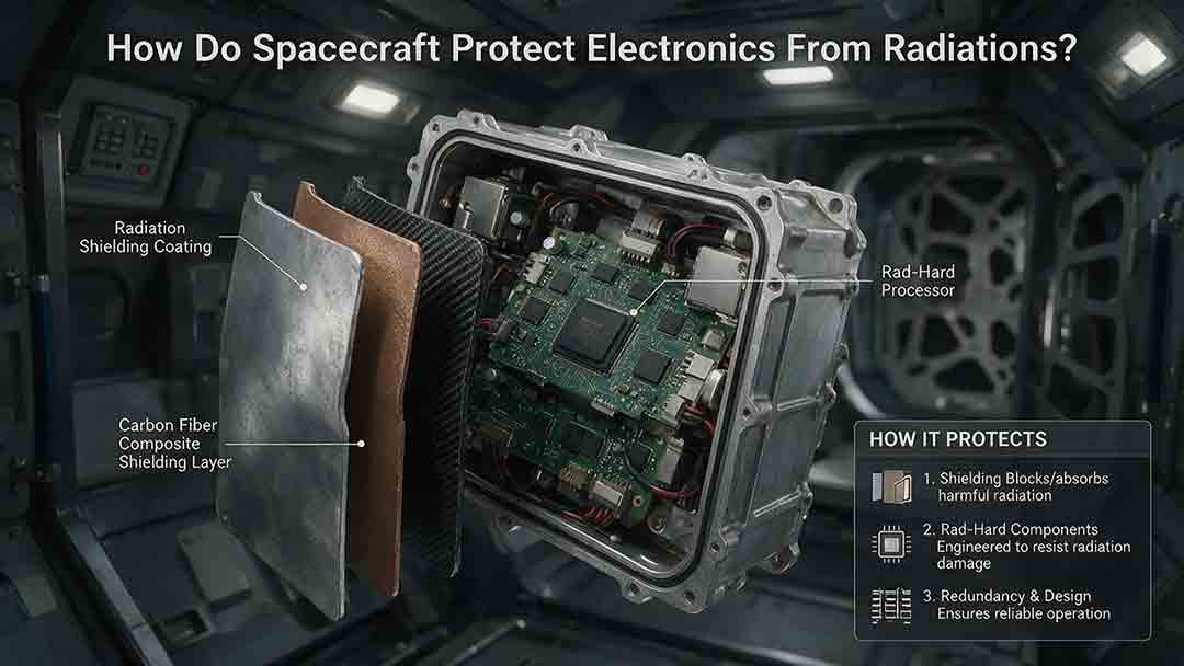
How Do Spacecraft Protect Electronics From Radiation?
Spacecraft protect electronics from radiation through a layered engineering strategy rather than a single protective material. This article explains how total ionizing dose, displacement damage, single-event effects, and spacecraft charging can disrupt computers, memory, sensors, and power systems. It examines the roles of radiation-hardened components, physical shielding, error-correcting memory, current limiting, watchdog timers, redundancy, fault isolation, and safe-mode recovery. Readers will also learn how engineers model mission-specific radiation environments, evaluate the quality of component test evidence, estimate dose margin, and choose different protection strategies for Earth orbit, deep space, and high-radiation destinations such as Jupiter. Practical comparison tables, a decision framework, real mission examples, a troubleshooting guide, and a design-review checklist show why reliable spacecraft must be able to prevent, detect, contain, and recover from radiation-related faults.
How Do Spacecraft Communicate With Earth?
Spacecraft communicate with Earth by sending encoded information through radio waves or laser light. This guide explains the complete path from an onboard instrument and computer to a transmitter, antenna, ground station, and mission-control center. It covers uplinks, downlinks, telemetry, tracking, direct-to-Earth communication, relay satellites, spacecraft crosslinks, and onboard data storage. Readers will also learn why signals weaken over distance, how communication delays are calculated, and how antenna gain, transmitter power, data rate, coding, pointing accuracy, and ground-network availability affect link reliability. Worked examples show how long a signal may take to travel between Mars and Earth and how much data can be returned during a scheduled contact. Real mission examples—including NASA’s Deep Space Network, the Mars Relay Network, the James Webb Space Telescope, and the DSOC optical demonstration—show how these engineering principles are applied in practice.
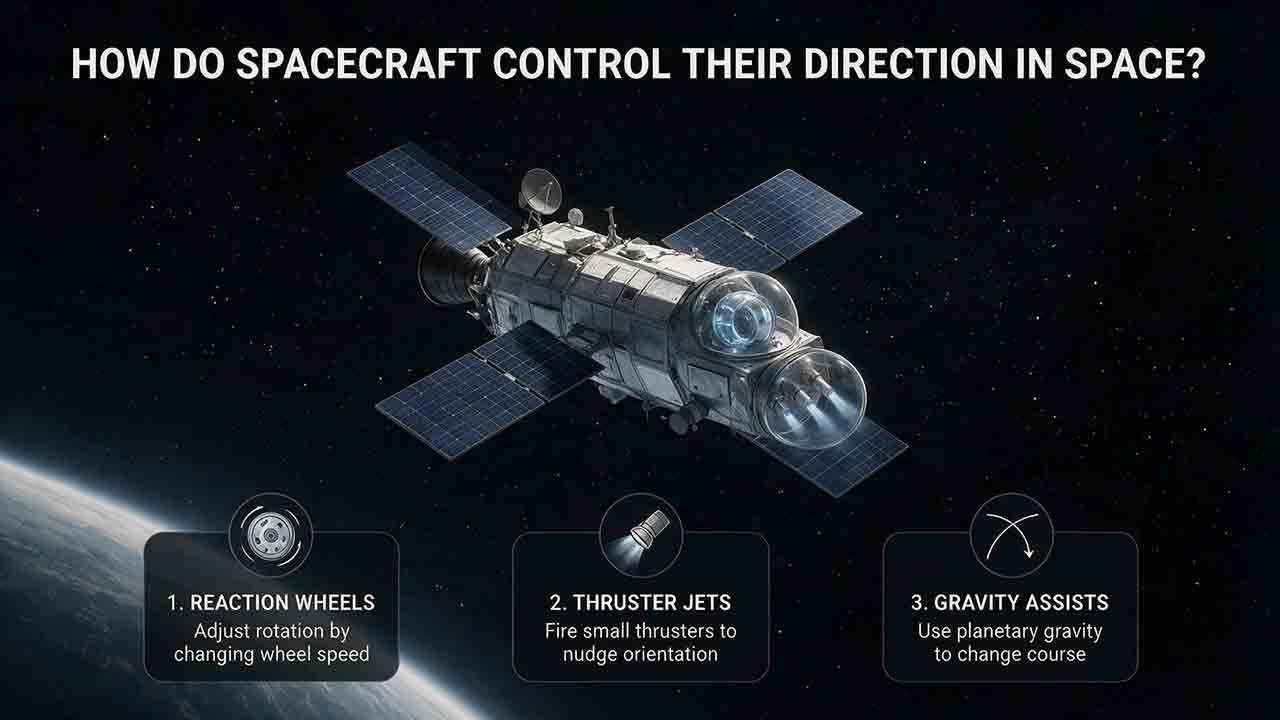
How Do Spacecraft Control Their Direction in Space?
Spacecraft control their direction through a coordinated attitude determination and control system. Sensors such as star trackers, Sun sensors, magnetometers, and gyroscopes estimate the spacecraft’s orientation, while onboard software compares that estimate with the required pointing direction. Reaction wheels, thrusters, control moment gyroscopes, and magnetic torquers then apply the necessary control torque. Some missions also use spin stabilization to resist unwanted changes in orientation. This article explains the difference between attitude and trajectory, follows the Sense → Estimate → Compare → Act → Verify control loop, and compares the strengths and limitations of major control methods. It also includes simplified torque and momentum calculations, real spacecraft examples from NASA and ESA missions, troubleshooting scenarios, and a practical framework for evaluating attitude-control architectures. Readers will learn why spacecraft pointing depends on an integrated system rather than a single steering device.
Explore More Topics
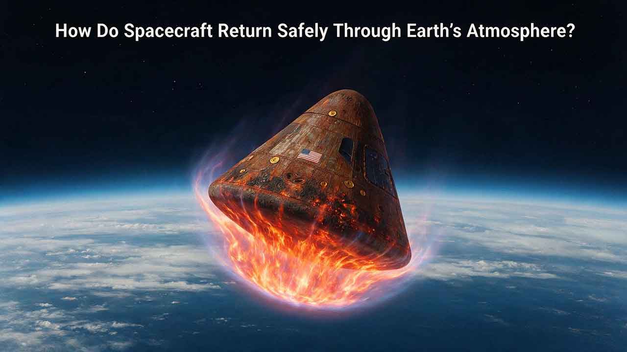
How Do Spacecraft Return Safely Through Earth’s Atmosphere?
Spacecraft return safely through Earth’s atmosphere by managing an enormous amount of energy through a carefully coordinated sequence of trajectory control, thermal protection, aerodynamic deceleration, landing, and recovery. This article explains how deorbit burns and entry corridors guide a spacecraft toward its landing region, why blunt heat shields reduce the danger of hypersonic heating, and how guidance systems control attitude, range, and structural loads. It includes an original comparison of low-Earth-orbit and lunar-return energy, a practical review of ablative and reusable heat-shield technologies, and the CosmoBasics Four-Layer Reentry Framework covering path, protection, control, descent, and recovery. Real-world lessons from Artemis I and the crewed Artemis II mission show why postflight inspection remains essential even after a successful splashdown. Readers will also learn how parachutes, wings, landing rockets, flotation systems, and recovery teams complete the return safely.
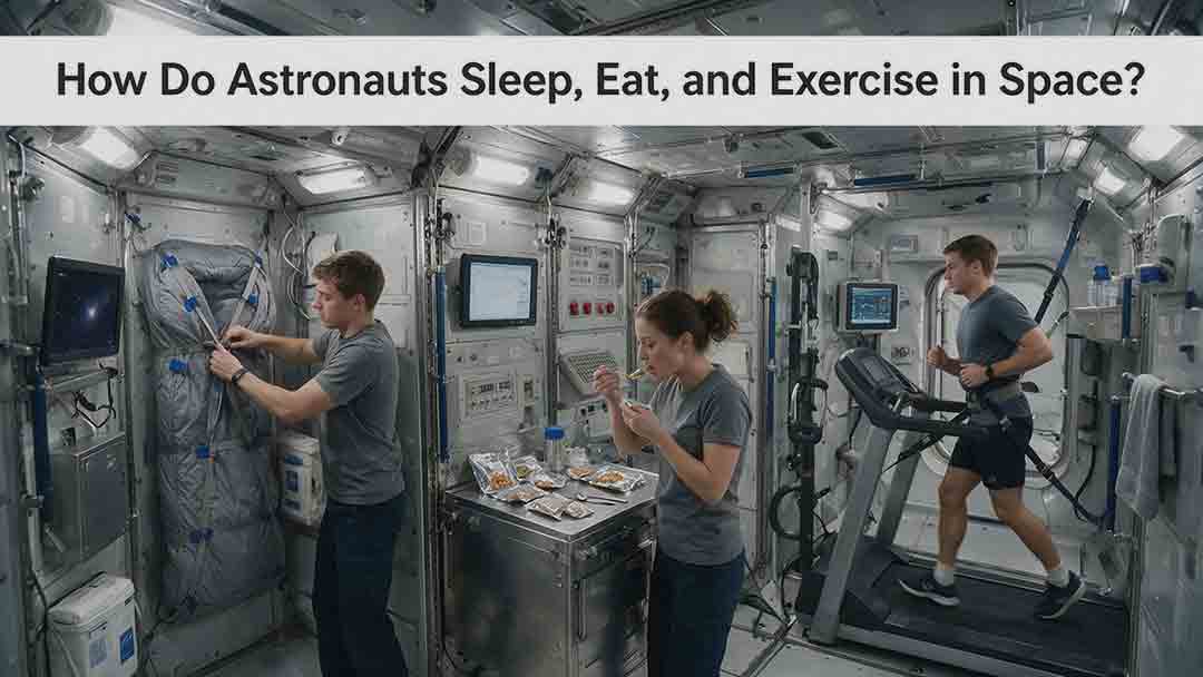
How Do Astronauts Sleep, Eat, and Exercise in Space?
Astronauts must redesign ordinary routines when they live in microgravity. This article explains how crew members sleep in secured bags inside ventilated quarters, prepare packaged meals without letting food or liquids drift through the cabin, and use specialized exercise equipment to protect their physical condition. It examines the roles of the Advanced Resistive Exercise Device, the T2 treadmill, and the CEVIS cycle ergometer, while clarifying the difference between active workout time and the full scheduled exercise period. Readers will also learn why tortillas are practical in space, how airflow affects sleep, why ordinary weights do not work normally in orbit, and how nutrition, rest, and exercise support one another. NASA and ESA sources provide the factual foundation, while original comparison tables and practical evaluation frameworks show how spacecraft systems replace functions normally supplied by gravity. The article also distinguishes current International Space Station practices from possible future Moon and Mars mission requirements.
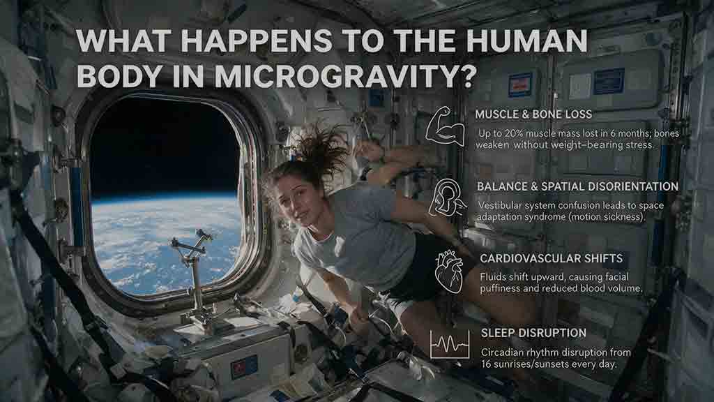
What Happens to the Human Body in Microgravity?
Microgravity changes the human body because fluids are no longer pulled toward the legs, muscles and bones receive less mechanical loading, and the brain loses gravity as a dependable orientation signal. This article explains how weightlessness affects balance, circulation, muscle strength, bone density, vision, blood, immunity, digestion, sleep, and spinal length. It also examines why astronauts may struggle to stand or walk after landing and how exercise, nutrition, monitoring, and rehabilitation help reduce these risks. Two original tools—the Load–Flow–Orientation Framework and the Gravity-Transition Readiness Matrix—connect physiological changes with real mission demands. Drawing on NASA standards, NASA technical reports, ESA materials, and peer-reviewed human spaceflight research, the guide clearly separates established observations from experimental countermeasures and unresolved questions. It also explains what these effects could mean for future missions to the Moon and Mars without treating population averages as predictions for individual astronauts.