How Do Spacecraft Communicate With Earth?

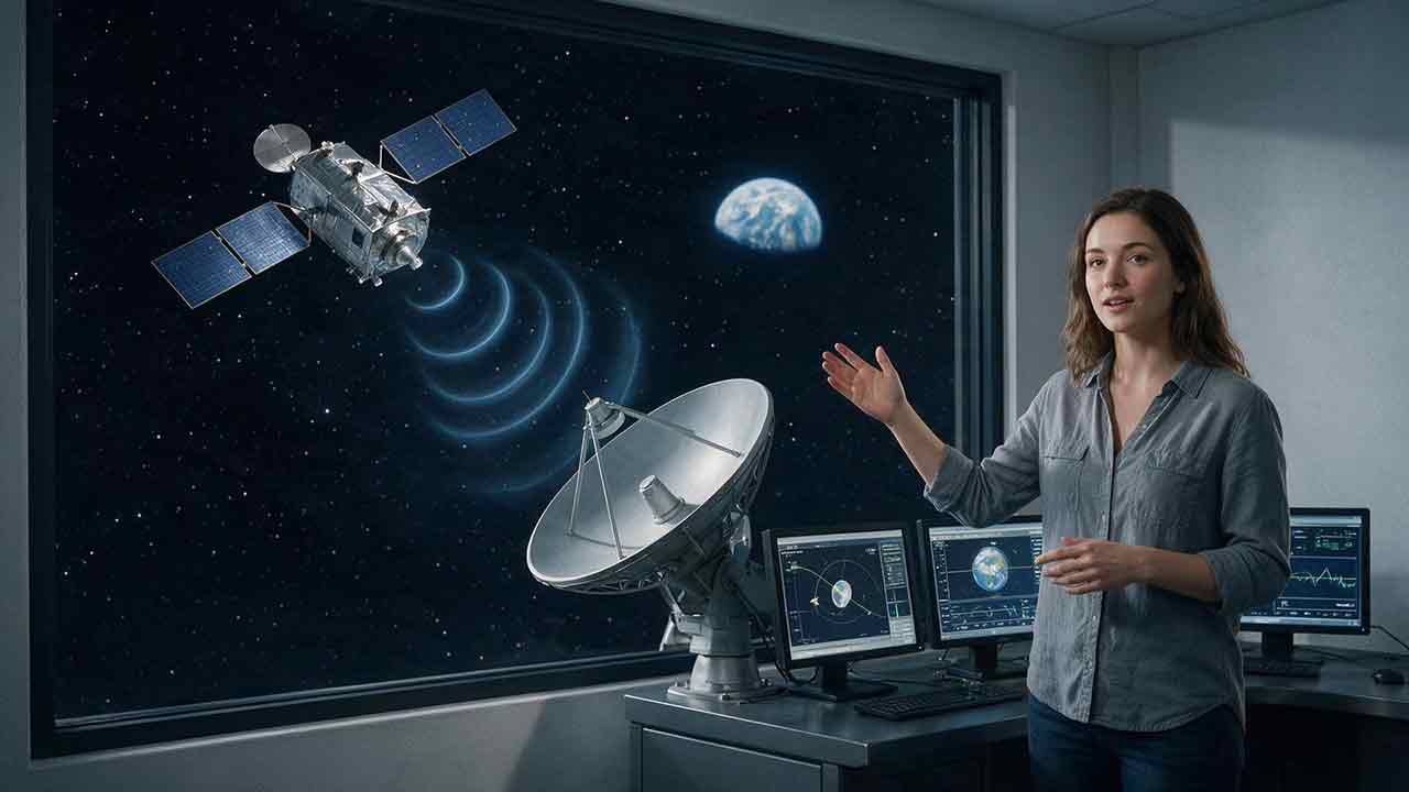
How Do Spacecraft Communicate With Earth?
Spacecraft communicate with Earth by encoding commands, health reports, images, and scientific measurements onto radio waves or laser light. An onboard antenna sends the signal directly to a ground station or through a relay spacecraft. Ground systems detect the weak transmission, correct recoverable errors, route the data to mission control, and send authorized commands back through an uplink.
Key Takeaways
- Radio-frequency communication remains the primary method used by most operational spacecraft.
- An uplink carries commands from Earth, while a downlink returns telemetry, science data, images, voice, or video.
- Spacecraft may communicate directly with Earth, through relay satellites, or across links between spacecraft.
- Distance weakens signals and creates an unavoidable delay because information cannot travel faster than light.
- Reliable communication depends on more than transmitter power: antennas, pointing, coding, data rate, ground-station access, storage, and autonomy all matter.
This article explains the complete communication chain, why distant signals become difficult to receive, how engineers estimate data return, and how real missions maintain contact when continuous communication is impossible.
End-to-end downlink
Instrument or spacecraft subsystem → onboard computer → packet and error-correction encoder → transmitter → spacecraft antenna → space link → ground antenna → receiver and decoder → mission control
End-to-end uplink
Mission control → authorized ground transmitter → ground antenna → space link → spacecraft antenna → receiver → command decoder → onboard computer
How Does a Spacecraft Communication Link Work End to End?
A spacecraft communication link can be understood as a seven-stage chain. Each stage must work well enough for the complete link to succeed.
1. The spacecraft creates information
A spacecraft continually produces information from several sources:
- Scientific instruments
- Navigation sensors
- Power, thermal, and propulsion systems
- Attitude-control equipment
- Onboard computers
- Cameras and other imaging systems
- Crew voice and video systems, when applicable
Some information is scientific, such as a planetary image or atmospheric measurement. Other information is operational telemetry that tells controllers whether the spacecraft is healthy.
A spacecraft cannot necessarily transmit everything immediately. Its computer must decide what to prioritize, what to compress, what to store, and what to discard if storage or downlink capacity becomes limited.
2. The onboard computer packages the data
Raw measurements are organized into digital packets or transfer frames. These structured units may contain:
- A source identifier
- A time tag
- A sequence number
- The payload data
- Error-detection information
- Routing or service information
Many agencies use communication standards developed through the Consultative Committee for Space Data Systems. CCSDS standards support compatible data exchange across spacecraft, ground stations, control centers, and cooperating space agencies.
A packet is not the radio signal itself. It is the organized digital information that will later be encoded and placed onto a radio-frequency or optical carrier.
3. Coding protects the information
The spacecraft adds controlled redundancy through channel coding. That extra information helps the receiver identify or correct some errors caused by weak signals, interference, noise, or temporary signal fading.
Stronger coding can make a link more reliable, but it also uses part of the available transmission capacity. Engineers therefore balance useful data volume against the amount of protection required.
Compression may also reduce the number of bits that must be transmitted. Lossless compression preserves the original data exactly, while carefully designed lossy compression may be acceptable for selected images or video products. The choice depends on the mission’s scientific and operational requirements.
4. The transmitter creates the radio or optical signal
A modulator places the encoded information onto an electromagnetic carrier. A power amplifier then raises the signal to the required transmission level.
Most spacecraft use radio-frequency communication. Optical communication systems use modulated laser light instead.
Both radio waves and light are electromagnetic radiation. Neither requires air or another physical medium to cross the vacuum of space.
5. The antenna or optical terminal points toward the receiver
Directional antennas concentrate energy toward a ground station or relay spacecraft. Optical terminals direct a much narrower laser beam.
The required pointing accuracy depends on beam width. A broad beam is easier to acquire but spreads energy over a larger region. A narrow beam can deliver more energy toward the receiver but is less tolerant of pointing error.
A spacecraft may point the entire vehicle, move an antenna on a gimbal, steer a phased array electronically, or combine several methods.
6. The signal crosses space and reaches a receiver
As a signal travels, its energy spreads. A distant receiving antenna captures only a small fraction of the original transmission.
The receiver amplifies the collected signal and filters out unwanted frequencies. Signal-processing equipment then attempts to identify the carrier, recover timing, demodulate the waveform, and decode the original bits.
Deep-space signals can arrive at Earth at extraordinarily low power levels. Large antennas, low-noise receivers, accurate pointing, careful scheduling, and advanced coding allow ground networks to recover useful data from those weak transmissions.
7. Mission systems reconstruct and use the data
Ground computers verify the decoded frames, restore packet order, attach timing information, and route each data product to the appropriate destination.
Engineering telemetry may go to spacecraft controllers. Navigation measurements may go to orbit-determination teams. Scientific observations may be forwarded to processing centers, researchers, and long-term archives.
Mission control can then prepare new commands. The uplink follows the same overall chain in reverse.
What Do Uplink, Downlink, Telemetry, and Tracking Mean?
These terms describe different communication functions rather than different types of spacecraft.
| Term | Meaning | Typical contents |
|---|---|---|
| Uplink | Transmission from Earth to a spacecraft | Commands, time updates, activity sequences, software or configuration data |
| Downlink | Transmission from a spacecraft toward Earth | Telemetry, science data, images, voice, video |
| Telemetry | Measurements describing spacecraft status or performance | Temperatures, voltages, memory status, orientation, subsystem states |
| Telecommand | An authorized instruction sent to the spacecraft | Point an instrument, begin an observation, change communication mode |
| Tracking | Measurements used to estimate position and motion | Range, Doppler, angular, and timing measurements |
| Crosslink | Communication between two spacecraft | Relay traffic, constellation routing, coordination, navigation data |
| Beacon or carrier | A simple detectable signal, sometimes with little or no data | Acquisition, emergency detection, basic status confirmation |
Tracking and communication often use the same radio contact, but their purposes differ. Communication transfers information; tracking measurements help determine where the spacecraft is and how it is moving.
What Information Does a Spacecraft Send to Earth?
Spacecraft data usually falls into several priority levels.
| Data category | What it tells the mission team | Typical priority |
|---|---|---|
| Emergency or safe-mode status | Whether the spacecraft is alive and stable | Highest |
| Housekeeping telemetry | Health of power, thermal, computer, and attitude systems | High |
| Command acknowledgments | Whether instructions were received or executed | High |
| Navigation and timing data | Position, velocity, clock state, and tracking information | High |
| Science observations | Instrument measurements, images, spectra, or radar products | Mission-dependent |
| Diagnostic logs | Detailed records used to investigate abnormal behavior | As required |
| Crew voice or video | Human communication and operational imagery | Mission-dependent |
During an emergency, a spacecraft may stop transmitting high-volume science files and switch to a low-rate health signal. The lower rate can improve the receiver’s ability to distinguish each bit from noise.
Stored science data can be returned later after the spacecraft reaches a more favorable geometry or obtains access to a suitable ground station.
Which Communication Path Does a Spacecraft Use?
The three main architectures are direct-to-Earth communication, relay communication, and crosslinks between spacecraft.
Direct-to-Earth communication
A direct-to-Earth link connects a spacecraft directly with a ground antenna.
This architecture avoids dependence on a relay. It is widely used by deep-space probes, observatories, planetary orbiters, and Earth-orbiting satellites.
The main limitation is visibility. A low-Earth-orbit satellite may pass over a particular ground station for only several minutes. A lander may lose Earth visibility when terrain, spacecraft structure, or planetary rotation blocks the line of sight.
Relay communication
A relay receives data from one spacecraft and forwards it to another destination.
Relay systems are especially useful when:
- A surface vehicle has limited power or antenna area
- A spacecraft cannot see Earth directly
- A low-orbiting spacecraft needs more frequent contact
- A crewed mission requires resilient communication coverage
- A constellation must route data toward available ground infrastructure
Relays can improve coverage and reduce the communication burden on a smaller spacecraft. They also introduce dependencies on scheduling, compatibility, relay availability, and another spacecraft’s operational health.
Crosslinks between spacecraft
A crosslink connects two spacecraft without first passing through a ground station.
Constellations may use crosslinks to route information from one satellite to another until the data reaches a spacecraft with ground visibility. Crosslinks can also support formation flying, distributed instruments, cooperative navigation, and planetary relay networks.
Store-and-forward communication
Store and forward is an operating method rather than a separate physical signal type.
A spacecraft records information in onboard memory, waits for a scheduled contact, and transmits the stored data later. This method is fundamental to missions that cannot remain continuously connected.
Communication architecture comparison
| Architecture | Best suited to | Main advantage | Main limitation |
|---|---|---|---|
| Direct to Earth | Deep-space probes, observatories, many individual satellites | Fewer intermediate systems | Contact depends on visibility and range |
| Earth-orbit relay | Human spaceflight and missions needing frequent coverage | Extends contact opportunities | Requires relay access and compatibility |
| Planetary relay | Rovers, landers, and surface stations | Reduces surface power and antenna requirements | Depends on an operational orbiter |
| Inter-satellite crosslink | Constellations and distributed spacecraft | Routes data through space | Adds network and pointing complexity |
| Store and forward | Missions with predictable communication gaps | Does not require continuous connectivity | Data reaches users later |
NASA’s Near Space Network coordinates direct-to-Earth and relay services for missions operating within 1.25 million miles of Earth, according to NASA’s description accessed in July 2026. NASA’s Deep Space Network supports communications and navigation for missions at the Moon and across deep space.
How Do Radio Waves Carry Spacecraft Data?
A spacecraft does not transmit digital ones and zeros as separate objects. Instead, it changes selected properties of a carrier wave in a controlled pattern.
This process is called modulation. The receiver measures those changes and reconstructs the digital information.
A simplified transmitting system contains:
- A data source
- A packet or frame processor
- A channel encoder
- A modulator
- A power amplifier
- An antenna
The receiving system performs the reverse functions:
- Collect the incoming energy
- Amplify the weak signal
- Filter unwanted signals
- acquire the carrier and timing
- Demodulate the waveform
- Decode and verify the data
- Route the recovered packets
Actual systems may divide these functions among several computers, radios, processors, and ground facilities.
Why Do Spacecraft Use Different Frequency Bands?
No single radio-frequency band is ideal for every mission.
| Communication option | Common applications | Advantages | Important limitations |
|---|---|---|---|
| VHF or UHF | Small satellites, local relay links, proximity operations | Mature hardware and relatively broad beams | Limited bandwidth and lower antenna gain for a given antenna size |
| S-band | Command, telemetry, tracking, and near-Earth services | Mature and widely supported | Lower potential throughput than higher-frequency bands |
| X-band | Deep-space and Earth-observation links | Established deep-space capability and useful antenna gain | Directional links require accurate pointing |
| Ka-band | High-rate science and exploration downlinks | Greater available bandwidth and high gain | More sensitivity to atmospheric loss and pointing |
| Optical or laser | High-volume experimental and selected operational links | Very high potential data return with narrow beams | Clouds, turbulence, acquisition, and pointing remain significant constraints |
These are general patterns, not universal rules. Frequency selection also depends on spectrum allocation, mission geometry, hardware heritage, antenna size, ground-network support, national authorization, and international coordination.
This article does not provide instructions for transmitting on spacecraft frequencies. Real transmissions require authorization and compliance with applicable spectrum regulations.
Why Do Spacecraft Carry More Than One Antenna?
The antenna that provides the fastest downlink under normal conditions may be unsuitable during an emergency.
Low-gain antennas
A low-gain antenna covers a relatively broad region of the sky. It is more tolerant of pointing uncertainty but does not concentrate much energy toward Earth.
Low-gain antennas are often valuable during launch, early operations, safe mode, or any condition in which the spacecraft cannot point precisely.
Medium-gain antennas
A medium-gain antenna provides a compromise between coverage and signal concentration. It can support useful command and telemetry rates without the narrow beam of a high-gain antenna.
High-gain antennas
A high-gain antenna concentrates energy into a narrow direction. It can support longer distances or higher data rates but must remain accurately pointed.
High-gain systems may use parabolic reflectors, phased arrays, reflectarrays, or other directional designs.
The core antenna tradeoff
| Antenna characteristic | Wider beam | Narrower beam |
|---|---|---|
| Pointing tolerance | Higher | Lower |
| Energy concentration | Lower | Higher |
| Typical achievable range or rate | Lower | Higher |
| Emergency usefulness | Often better | Often limited |
| Attitude-control demand | Lower | Higher |
A robust spacecraft may therefore use a narrow high-gain antenna for routine science return and a broader low-gain antenna for recovery or emergency communication.
Why Do Spacecraft Signals Become So Weak?
In free space, signal energy spreads across an increasingly large area as distance increases.
For a simplified comparison in which the antennas, frequency, pointing, and other conditions remain unchanged:
[
P_r \propto \frac{1}{d^2}
]
where:
- (P_r) is received power;
- (d) is the separation between transmitter and receiver.
If the distance doubles, the energy is spread over approximately four times the area. The receiving system collects about one-quarter as much power under the simplified assumptions.
How Distance Changes Received Signal Power
| Distance | Relative received power |
|---|---|
| (d) | 100% |
| (2d) | 25% |
| (4d) | 6.25% |
| (10d) | 1% |
This is not a complete link calculation. It excludes antenna gain, frequency, atmospheric loss, polarization, pointing error, coding performance, and receiver noise.
It nevertheless explains why long-distance communication often requires large ground antennas, lower data rates, stronger coding, and careful antenna pointing.
What Is a Communication Link Budget?
A link budget is an accounting of the gains, losses, and performance requirements between a transmitter and receiver.
A mission-specific link budget may include:
- Transmitter output power
- Cable and circuit losses
- Transmitting antenna gain
- Free-space path loss
- Atmospheric loss
- Polarization mismatch
- Pointing loss
- Receiving antenna gain
- Receiver noise temperature
- Modulation and coding performance
- Required bit-error performance
- Implementation losses
- Operational margin
A positive calculated margin means the predicted signal exceeds the minimum required level by the stated amount under the modeled conditions.
Engineers can improve a weak link by changing one or more variables:
- Increase transmitter power
- Use a higher-gain antenna
- Improve pointing
- Reduce the data rate
- Use stronger error-correction coding
- Use a larger ground antenna
- Combine signals from multiple antennas
- Select a more favorable contact period
- Reduce avoidable system losses
Every improvement has a cost. Higher power creates electrical and thermal demands. Larger antennas add mass and mechanical constraints. Lower data rates increase the time required to return information.
How Much Data Can a Spacecraft Actually Return?
A quoted maximum data rate does not reveal how much science data a mission can return in a day.
A more useful first estimate is:
[
\text{Returnable data}
\approx
\text{usable contact time}
\times
\text{effective data rate}
]
The effective data rate is lower than the raw physical-layer rate because some capacity is used for:
- Synchronization
- Error-correction coding
- Packet and frame headers
- Engineering telemetry
- Link acquisition
- Repeated or rejected data
- Operational interruptions
- Ground-system transitions
Worked example: data returned during one contact
Assume a spacecraft receives a four-hour ground-station allocation, but only 3.5 hours are usable after acquisition and operational overhead.
Assume the average effective science-data rate is 2 megabits per second:
[
3.5\ \text{hours}
\times
3{,}600\ \text{seconds per hour}
\times
2\ \text{Mb/s}
25{,}200\ \text{Mb}
]
Using eight bits per byte:
[
25{,}200\ \text{Mb}
\div 8
3{,}150\ \text{MB}
]
The contact could return approximately 3.15 gigabytes under those assumptions.
This is an estimate, not a guaranteed result. Actual return depends on protocol overhead, link conditions, mission priorities, and whether the assumed rate can be maintained throughout the usable contact.
Why average capacity matters
A spacecraft may temporarily generate data faster than it can transmit. Onboard storage absorbs the difference.
However, if the long-term data-production rate remains higher than average downlink capacity, the recorder will eventually fill. The mission must then change its observation plan, compress more data, obtain additional ground time, raise effective downlink capacity, or accept that some observations cannot be retained.
Transmission time for a 1 GB file
Using the decimal convention:
[
1\ \text{GB}=8{,}000\ \text{Mb}
]
Ignoring protocol and coding overhead:
| Effective downlink rate | Minimum transmission time |
|---|---|
| 100 kilobits per second | About 22.2 hours |
| 1 megabit per second | About 2.2 hours |
| 10 megabits per second | About 13.3 minutes |
| 100 megabits per second | About 1.3 minutes |
Real transfers take longer than this ideal calculation.
How Long Does a Spacecraft Signal Take to Reach Earth?
Communication delay is set primarily by distance:
[
t=\frac{d}{c}
]
where:
- (t) is one-way propagation time;
- (d) is distance;
- (c) is the speed of light, approximately (299{,}792\ \text{km/s}) in a vacuum.
Radio and optical signals travel at essentially the same speed through space. Optical communication can carry more data per second, but it does not make information cross the distance faster.
Typical One-Way Propagation Delay, Excluding Processing Time
| Destination or region | Typical one-way propagation delay | Important qualification |
|---|---|---|
| Low Earth orbit | A few to several tens of milliseconds | Depends on altitude, geometry, and signal path |
| Geostationary orbit | About 0.12 seconds for a direct one-way path | End-to-end services also include routing and processing |
| Moon | About 1.3 seconds near the average Earth–Moon distance | The lunar distance changes over time |
| Mars | About 3 to 22.4 minutes | Changes continuously with planetary positions |
| Outer solar system | Tens of minutes to several hours | Strongly mission- and date-dependent |
NASA’s Mars Relay Network overview gives an approximate Earth–Mars one-way light-time range of 3 to 22.4 minutes, depending on the planets’ positions.
Worked Example: One-Way Signal Time From Mars
At an illustrative separation of 225 million kilometers:
[
t=
\frac{225{,}000{,}000\ \text{km}}
{299{,}792\ \text{km/s}}
\approx
750.5\ \text{s}
]
[
750.5\ \text{s}
\approx
12.5\ \text{minutes}
]
A command would take about 12.5 minutes to arrive. A response could not return sooner than approximately another 12.5 minutes, even if the spacecraft replied immediately.
The minimum round-trip propagation time would therefore be about 25 minutes, excluding command processing, spacecraft activity, ground analysis, and network routing.
This delay is why a Mars rover cannot be driven like a remote-controlled car. Controllers send plans and goals, while onboard systems handle immediate timing, hazard responses, and portions of navigation.
How Do Ground Networks Maintain Contact?
A single ground antenna cannot see every spacecraft continuously. Earth rotates, spacecraft move, terrain and planetary bodies block lines of sight, and many missions compete for access to specialized antennas.
Ground networks address these limitations through geographically separated sites, relay spacecraft, shared scheduling, onboard storage, and international cross-support.
NASA’s Deep Space Network
NASA’s Deep Space Network has complexes near:
- Goldstone, California
- Madrid, Spain
- Canberra, Australia
The three locations are separated by approximately 120 degrees of longitude. As Earth rotates, one complex can assume visibility after another loses it.
NASA and JPL describe the network as supporting communication, tracking, navigation, and radio-science activities for deep-space missions. Current network information is available from NASA’s Deep Space Network page and JPL’s DSN mission page.
Geographic coverage does not mean every spacecraft receives an uninterrupted dedicated antenna. Contacts must still be scheduled among missions, and antenna availability depends on geometry, equipment, priority, frequency support, and network demand.
NASA’s Near Space Network
NASA states that the Near Space Network coordinates direct-to-Earth and space-relay communication and navigation services for missions within 1.25 million miles of Earth.
The network combines government and commercial assets. Its supported missions include Earth-observing spacecraft, science missions, technology demonstrations, launches, human spaceflight, and exploration activities.
Service boundaries and available capabilities can evolve, so mission planners must use current network documentation rather than relying on a permanent simplified division between “near” and “deep” space.
ESA’s ESTRACK network
The European Space Agency’s ESTRACK network links spacecraft with the European Space Operations Centre.
ESA describes the network’s essential tasks as transmitting commands and receiving scientific data and spacecraft-status information. ESTRACK supports missions near Earth, at Sun–Earth Lagrange regions, and in deep space.
International missions may receive support from more than one agency’s network under established cross-support arrangements.
How Does Mission Control Know Whether a Command Worked?
Transmitting a command does not prove that the spacecraft received or executed it.
Controllers may look for several forms of confirmation:
- The ground station reports a successful uplink transmission.
- Spacecraft telemetry shows that the receiver locked onto the uplink.
- A command counter or acknowledgment field changes.
- The relevant subsystem reports a new state.
- Instrument data confirms that the requested activity began.
- Tracking data shows the expected result of a maneuver.
- Event logs confirm completion or identify an error.
The exact confirmation chain depends on mission design.
Commands may also be time-tagged. Mission teams can upload an activity sequence during one contact and allow the spacecraft to execute it later, after direct communication has ended.
What Happens When a Spacecraft Cannot Contact Earth?
A temporary loss of communication does not automatically mean that the mission has failed.
Possible causes include:
- No ground-station contact was scheduled
- Earth is below the local horizon
- A planet, moon, terrain feature, or spacecraft structure blocks the signal
- The antenna is pointed away from the receiver
- The spacecraft has entered safe mode
- Available electrical power is limited
- The spacecraft is using an unexpected communication mode
- Ground equipment is unavailable
- Radio noise is unusually high
- Cloud cover blocks an optical link
- The Sun is close to the line of sight
- A transmitter, receiver, amplifier, cable, antenna, or computer has malfunctioned
Spacecraft are generally designed to tolerate expected communication gaps. They may continue following stored instructions, preserve data, repeat a beacon, or wait for the next planned opportunity.
Deep-space missions require greater autonomy because controllers cannot respond immediately to rapidly developing conditions.
What Factors Do Mission Teams Investigate After a Communication Problem?
The following table is an educational diagnostic framework. It is not an operating procedure for a real spacecraft or ground station.
| Observed symptom | Possible explanations | General factors authorized mission teams may investigate |
|---|---|---|
| No carrier is detected | Incorrect pointing prediction, blocked line of sight, spacecraft not transmitting, unexpected mode | Compare documented geometry, expected frequency, spacecraft state, and authorized ground observations |
| Carrier appears but valid data does not | Weak signal, synchronization loss, coding mismatch, incorrect mode | Verify whether ground configuration matches the documented spacecraft transmission mode |
| Contact is intermittent | Marginal link, changing geometry, attitude motion, interference | Compare signal changes with attitude, range, antenna pattern, and environmental data |
| Commands appear to arrive but downlink is weak | Transmitter, amplifier, antenna, or pointing problem | Review telemetry and assess whether an approved lower-rate or alternate-antenna mode is available |
| Telemetry arrives but science files do not | Recorder backlog, priority rules, insufficient contact time | Review the downlink plan, recorder state, and science-data priority |
| Optical acquisition fails | Cloud, turbulence, beacon, timing, or pointing issue | Evaluate authorized optical-site weather and documented acquisition conditions |
| Recovered data repeatedly fails verification | Noise, configuration mismatch, packet corruption, timing error | Compare configuration records and determine whether retransmission is supported |
Real anomaly response is performed by authorized personnel using mission-specific procedures, verified telemetry, network logs, and approved command authority.
Which Is Better: Radio or Laser Communication?
Neither is universally better.
Radio communication is mature, broadly supported, and generally less vulnerable to cloud cover. Optical communication can provide much higher data-return capacity with narrow beams and potentially smaller terminals for some missions.
| Criterion | Radio-frequency communication | Optical communication |
|---|---|---|
| Operational maturity | Very high | Increasing, with demonstrations and selected operational applications |
| Potential data rate | Moderate to high | Very high |
| Beam width | Generally wider | Extremely narrow |
| Pointing demand | Moderate to demanding | Extremely demanding |
| Cloud sensitivity | Usually limited at common spacecraft bands | High for Earth-based optical links |
| Atmospheric turbulence | Frequency-dependent effects | Important concern |
| Ground terminal | Radio antenna or dish array | Optical telescope |
| Acquisition difficulty | Well understood | More demanding |
| Typical role | Command, telemetry, tracking, and dependable mission support | High-volume downlink or specialized high-capacity links |
| Backup value | Often the baseline recovery system | Usually paired with radio in early or risk-sensitive applications |
NASA’s optical communications overview explains that optical systems can increase data rates but require precise beam pointing and must contend with atmospheric interference such as clouds.
NASA also notes that “faster” refers to the amount of data transferred per second. Laser data does not travel through space faster than radio data.
How practical is laser communication now?
Radio remains the primary communication method for most spacecraft. Optical communication has progressed beyond laboratory research into multiple flight demonstrations and selected operational applications.
The technology still faces practical constraints:
- Narrow-beam acquisition
- Precise pointing and tracking
- Cloud cover
- Atmospheric turbulence
- Availability of suitable optical ground sites
- Need for operational scheduling and fallback paths
A high-data-rate mission may benefit from optical communication as an addition to radio. It should not be assumed that an optical link can serve as the only safe communication path in every mission or weather condition.
Real-World Example: NASA’s DSOC Demonstration
NASA’s Deep Space Optical Communications experiment flew aboard the Psyche spacecraft as a technology demonstration.
On December 11, 2023, DSOC transmitted an ultra-high-definition test video from approximately 31 million kilometers away at the system’s maximum reported rate of 267 megabits per second.
That result applied to a specific experimental configuration and distance. It was not a universal rate for deep-space optical systems.
NASA and JPL report that DSOC exceeded its technical goals and concluded on September 2, 2025. The project is now identified as a past technology demonstration. See JPL’s DSOC mission record for the current status.
The experiment demonstrated the potential of high-bandwidth optical communication, not the elimination of range, weather, pointing, or ground-infrastructure constraints.
Real-World Example: How the Mars Relay Network Works
A Mars rover can communicate directly with Earth, but a direct link from the surface is constrained by power, antenna size, planetary rotation, and distance.
A relay path works as follows:
- The rover records science and engineering data.
- A Mars orbiter passes above the rover.
- The rover transmits over a shorter local link.
- The orbiter receives and stores the data.
- The orbiter later points its larger communication system toward Earth.
- A deep-space ground station receives the transmission.
- Ground systems route the data to the rover team.
NASA’s Mars Relay Network overview, accessed in July 2026, describes four Mars orbiters relaying data for the Curiosity and Perseverance rovers. NASA states that nearby rover-to-orbiter links can operate at rates of up to 2 megabits per second under supported conditions.
The number and identity of operational relay orbiters can change. A current mission page should therefore be checked before publishing a permanent list.
The architecture illustrates a valuable engineering principle: use a short local link from the resource-limited surface vehicle, then assign the demanding long-distance transmission to an orbiter with more power, larger radio equipment, and more regular Earth contact.
Real-World Example: How the James Webb Space Telescope Communicates
The James Webb Space Telescope operates near the Sun–Earth L2 region, approximately 1.5 million kilometers from Earth.
Webb communicates through NASA’s Deep Space Network. NASA’s Webb communication overview states that:
- S-band is used for commands and engineering telemetry.
- Ka-band is used to downlink stored science and engineering data.
- The mission operations center connects with Webb at least two to three times in a typical 24-hour period.
- Most contact periods last approximately two to six hours.
- Webb stores data on a solid-state recorder between contacts.
These figures describe NASA’s published operating pattern at the time of the July 2026 review. Contact schedules may change with mission needs and Deep Space Network availability.
Webb shows that a spacecraft can perform continuous scientific work without maintaining a continuous high-rate connection. Observations are preplanned, data is stored onboard, and the recorder is emptied during scheduled contacts.
How Should a Mission Choose a Communication Architecture?
A useful decision framework begins with six questions.
1. What is the maximum communication distance?
Greater distance increases path loss and delay. A low-Earth-orbit satellite, lunar lander, Mars rover, and outer-planet probe cannot use the same assumptions.
2. How much data will the spacecraft produce?
The design should compare expected daily data production with average returnable capacity—not merely the transmitter’s maximum advertised rate.
3. How often is contact required?
A mostly autonomous science mission may tolerate occasional contacts. A crewed mission or time-sensitive platform may need relays, multiple ground sites, and redundant links.
4. What spacecraft resources are available?
Important constraints include:
- Electrical power
- Thermal rejection
- Antenna area
- Terminal mass
- Pointing accuracy
- Onboard memory
- Computer capacity
5. What link environment must be tolerated?
The design must consider:
- Range variation
- Line-of-sight interruptions
- Atmospheric loss
- Cloud and turbulence for optical links
- Solar conjunction
- Radio-noise environment
- Ground-network competition
6. What happens if the primary link fails?
A resilient architecture may include:
- A low-gain backup antenna
- More than one radio
- Multiple communication modes
- Multiple ground sites
- Relay and direct-to-Earth options
- Onboard storage
- Safe-mode telemetry
- Autonomous fault protection
- Radio backup for an optical link
Communication-Path Decision Table
| Mission condition | Usually favored approach |
|---|---|
| Small satellite with short ground passes | Multiple ground stations, store and forward, or relay access |
| Deep-space probe with modest data production | High-gain direct-to-Earth radio |
| Mars surface vehicle | Local relay through Mars orbiters with limited direct capability |
| High-volume observatory | High-rate directional radio, optical communication, or a hybrid system |
| Mission with long predictable gaps | Onboard storage and autonomous scheduling |
| Human mission requiring frequent contact | Multiple networks, relays, and redundant links |
| Optical mission exposed to clouds | Geographically diverse optical sites and radio fallback |
This table provides a starting point, not a mission design. The final architecture must be supported by detailed link budgets, regulatory coordination, hardware testing, and verified network compatibility.
Mission Communication Review Checklist
Use this checklist to compare publicly documented mission architectures. It is not a substitute for a mission-specific link budget, safety review, or spectrum-coordination process.
Mission requirements
- What is the minimum and maximum distance?
- How much data is generated per hour or per day?
- How quickly must commands receive confirmation?
- How frequently must the spacecraft contact Earth?
- Which information has the highest priority?
- Is continuous communication truly required?
Spacecraft resources
- How much transmitter power is available?
- What antenna or optical-terminal size is practical?
- How accurately can the spacecraft point?
- How much onboard storage is available?
- Can the thermal system support long transmissions?
- Is a low-rate emergency communication mode available?
Link environment
- Is direct line of sight available?
- Does the path pass through an atmosphere?
- Could terrain or spacecraft structure block the beam?
- Is cloud cover relevant to an optical link?
- How much does distance vary?
- Are solar conjunctions or other outages expected?
Network and resilience
- Which authorized ground stations support the required bands?
- Is relay capacity available?
- Are multiple geographic sites available?
- Can the spacecraft communicate through more than one antenna?
- Is there a radio fallback for an optical system?
- Can the spacecraft operate safely during long communication gaps?
- Are the flight and ground protocols compatible?
- Has realistic operational margin been included?
Who Is This Article For?
This guide is intended for:
- General readers learning how spacecraft systems work
- Students studying introductory space engineering
- Science communicators checking terminology
- Mission enthusiasts interpreting public mission documentation
- Editors comparing communication architectures at a conceptual level
It is not a replacement for:
- Professional spacecraft-system engineering
- A certified link-budget analysis
- Spectrum licensing or coordination advice
- Ground-station operating procedures
- Mission command authorization
- Cybersecurity or command-authentication design
- Manufacturer-specific technical documentation
Mistake 1: Assuming spacecraft are always online
Many spacecraft communicate only during scheduled windows. They continue operating through stored instructions and onboard autonomy.
Mistake 2: Treating delay as a bandwidth problem
A higher data rate can return more information per second. It cannot remove the light-travel time caused by distance.
Mistake 3: Assuming laser signals travel faster than radio signals
Both are electromagnetic radiation and travel at essentially the same speed in a vacuum.
Mistake 4: Assuming higher frequencies are always better
Higher frequencies can provide more bandwidth and antenna gain, but they may increase pointing and atmospheric challenges.
Mistake 5: Focusing only on transmitter power
A successful link also depends on antenna gain, frequency, coding, data rate, receiver noise, geometry, polarization, and ground infrastructure.
Mistake 6: Assuming a long contact equals high data return
Only the usable part of the contact contributes to data transfer. Acquisition, overhead, interruptions, telemetry, and changing link conditions reduce effective capacity.
Mistake 7: Treating loss of signal as proof of spacecraft failure
A spacecraft may be outside a contact window, behind a planet, in safe mode, using another antenna, or waiting for a scheduled pass.
What This Article Does Not Claim
This article explains publicly documented spacecraft communication principles and examples.
It does not claim access to:
- Private mission telemetry
- Proprietary spacecraft designs
- Unpublished link budgets
- Restricted ground-network procedures
- Mission command credentials
- Confidential anomaly reports
It also does not provide instructions for unauthorized transmissions, interference, command access, or operation of real mission infrastructure.
Actual systems require qualified engineering analysis, verified hardware data, environmental testing, spectrum authorization, network agreements, security controls, and mission-specific procedures.
How This Article Was Reviewed
The technical explanation was checked against publicly available material from NASA, NASA’s Jet Propulsion Laboratory, ESA, and CCSDS.
The review process included:
- Comparing definitions across first-party space-agency sources
- Checking the seven-stage communication flow for internal consistency
- Recalculating the distance, delay, and data-volume examples
- Separating general physical principles from mission-specific performance
- Reviewing dynamic mission claims against sources available on July 31, 2026
- Removing unsupported expert claims and unverified operational advice
No independent technical reviewer is claimed unless a named reviewer is added with their consent and verifiable qualifications.
Why You Can Trust This Article
The article labels estimates and shows their assumptions rather than presenting them as measured mission results.
Mission-specific numbers are linked to first-party documentation and dated where their status may change. Experimental achievements, including DSOC performance, are not presented as guaranteed capability for other spacecraft.
The article also avoids implying access to private mission systems and does not convert general troubleshooting concepts into instructions for operating or accessing real communication networks.
The Practical Conclusion
Spacecraft communicate with Earth through an integrated chain of computers, coding, transmitters, antennas, space links, ground networks, and mission-control systems. No single component determines success.
For a near-Earth spacecraft, the next step is to compare direct ground contacts with relay coverage. For a lunar or deep-space mission, begin with distance, delay, data production, antenna gain, power, storage, and ground-network availability. For a high-volume mission, evaluate optical communication as a complement to proven radio systems rather than assuming it is an automatic replacement.
Can spacecraft communicate without radio waves?
Yes. Spacecraft can use optical communication, which encodes data onto laser light. Optical systems can support high data rates, but precise pointing, cloud cover, atmospheric turbulence, and specialized ground terminals affect availability.
Can a spacecraft communicate when it is behind a planet?
Not through a direct line-of-sight link to Earth. The spacecraft must store its data, wait until visibility returns, or use a relay spacecraft with a clear path.
Why do spacecraft need large dish antennas?
A large directional antenna concentrates transmitted energy and collects more of a weak incoming signal. This can improve range, data rate, or reliability, but it also creates pointing, mass, cost, and scheduling requirements.
Can astronauts on Mars have a normal real-time conversation with Earth?
No. Earth–Mars one-way propagation delay varies from roughly 3 to 22.4 minutes. A reply may therefore arrive many minutes after a message was sent, even before operational and processing delays are included.
What happens during solar conjunction?
During solar conjunction, a spacecraft appears close to the Sun from Earth’s viewpoint. Solar radio noise and propagation effects can make communication less reliable. Mission teams may reduce commanding and allow the spacecraft to follow stored plans until the geometry improves.
Do spacecraft use the same internet as people on Earth?
Some missions use packets, networking concepts, and standardized protocols, but space communication must tolerate weak signals, long delays, interrupted links, and unequal uplink and downlink rates. Delay-tolerant and store-and-forward methods are often more suitable than assumptions used by ordinary terrestrial internet services.
Sources
- NASA — Deep Space Network
- NASA JPL — Deep Space Network
- NASA — Near Space Network
- NASA Science — Mars Relay Network
- NASA Science — How Do We Communicate With Webb?
- NASA — Optical Communications
- NASA — Laser Communications
- NASA JPL — Deep Space Optical Communications
- ESA — ESTRACK Global Ground Station Network
- CCSDS — Overview of Space Communications Protocols
- CCSDS — Space Data Link Protocols: Summary of Concept and Rationale
- NASA JPL — Telecommunications Link Design Handbook
Sources and dynamic mission information last checked July 31, 2026.
More from Spacecraft Engineering
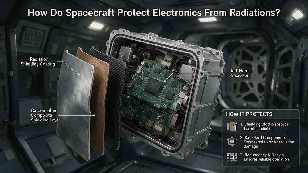
How Do Spacecraft Protect Electronics From Radiation?
Spacecraft protect electronics from radiation through a layered engineering strategy rather than a single protective material. This article explains how total ionizing dose, displacement damage, single-event effects, and spacecraft charging can disrupt computers, memory, sensors, and power systems. It examines the roles of radiation-hardened components, physical shielding, error-correcting memory, current limiting, watchdog timers, redundancy, fault isolation, and safe-mode recovery. Readers will also learn how engineers model mission-specific radiation environments, evaluate the quality of component test evidence, estimate dose margin, and choose different protection strategies for Earth orbit, deep space, and high-radiation destinations such as Jupiter. Practical comparison tables, a decision framework, real mission examples, a troubleshooting guide, and a design-review checklist show why reliable spacecraft must be able to prevent, detect, contain, and recover from radiation-related faults.
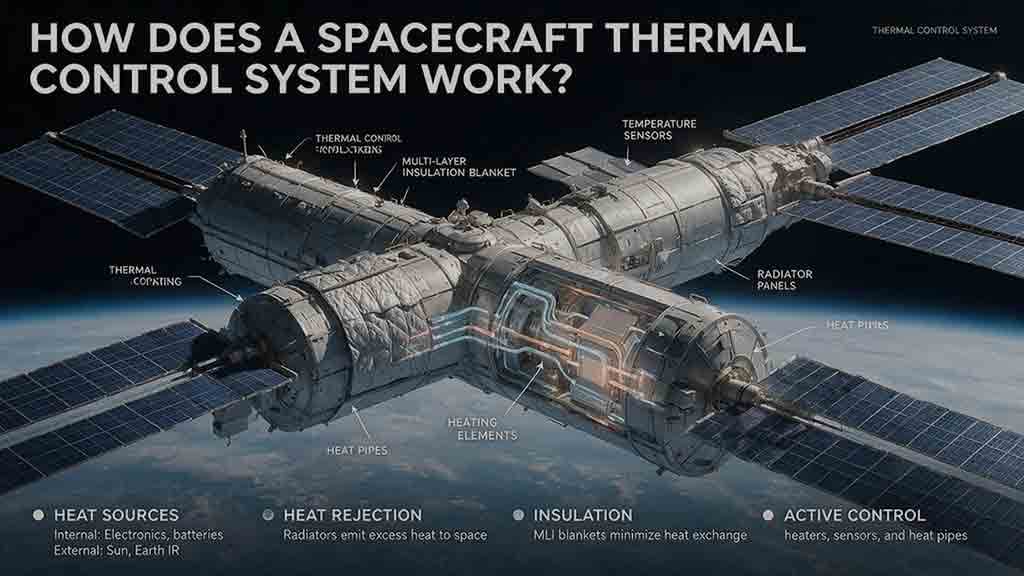
How Does a Spacecraft Thermal Control System Work?
A spacecraft thermal control system keeps onboard equipment within safe operating and survival temperatures by controlling how heat is absorbed, generated, transported, stored, and released. This guide explains how passive technologies—including multilayer insulation, thermal coatings, heat pipes, straps, and radiators—work alongside active systems such as heaters, temperature sensors, cryocoolers, and pumped fluid loops. It introduces the original Protect–Move–Reject–Trim–Verify framework for understanding complete spacecraft heat paths and provides practical tools for evaluating thermal designs. Readers will also find a worked radiator-sizing example, a thermal-resistance calculation, mission-specific selection guidance, common design mistakes, troubleshooting methods, and real examples from the James Webb Space Telescope, International Space Station, and Europa Clipper. Based on publicly available NASA and ESA documentation, the article distinguishes simplified educational calculations from actual flight-design analysis while showing why spacecraft must be protected from both overheating and excessive cooling.
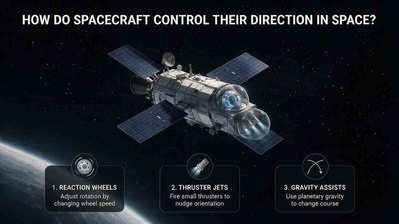
How Do Spacecraft Control Their Direction in Space?
Spacecraft control their direction through a coordinated attitude determination and control system. Sensors such as star trackers, Sun sensors, magnetometers, and gyroscopes estimate the spacecraft’s orientation, while onboard software compares that estimate with the required pointing direction. Reaction wheels, thrusters, control moment gyroscopes, and magnetic torquers then apply the necessary control torque. Some missions also use spin stabilization to resist unwanted changes in orientation. This article explains the difference between attitude and trajectory, follows the Sense → Estimate → Compare → Act → Verify control loop, and compares the strengths and limitations of major control methods. It also includes simplified torque and momentum calculations, real spacecraft examples from NASA and ESA missions, troubleshooting scenarios, and a practical framework for evaluating attitude-control architectures. Readers will learn why spacecraft pointing depends on an integrated system rather than a single steering device.
Explore More Topics
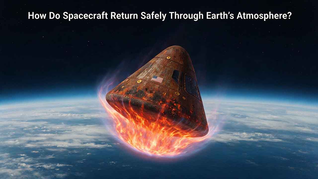
How Do Spacecraft Return Safely Through Earth’s Atmosphere?
Spacecraft return safely through Earth’s atmosphere by managing an enormous amount of energy through a carefully coordinated sequence of trajectory control, thermal protection, aerodynamic deceleration, landing, and recovery. This article explains how deorbit burns and entry corridors guide a spacecraft toward its landing region, why blunt heat shields reduce the danger of hypersonic heating, and how guidance systems control attitude, range, and structural loads. It includes an original comparison of low-Earth-orbit and lunar-return energy, a practical review of ablative and reusable heat-shield technologies, and the CosmoBasics Four-Layer Reentry Framework covering path, protection, control, descent, and recovery. Real-world lessons from Artemis I and the crewed Artemis II mission show why postflight inspection remains essential even after a successful splashdown. Readers will also learn how parachutes, wings, landing rockets, flotation systems, and recovery teams complete the return safely.

How Do Astronauts Sleep, Eat, and Exercise in Space?
Astronauts must redesign ordinary routines when they live in microgravity. This article explains how crew members sleep in secured bags inside ventilated quarters, prepare packaged meals without letting food or liquids drift through the cabin, and use specialized exercise equipment to protect their physical condition. It examines the roles of the Advanced Resistive Exercise Device, the T2 treadmill, and the CEVIS cycle ergometer, while clarifying the difference between active workout time and the full scheduled exercise period. Readers will also learn why tortillas are practical in space, how airflow affects sleep, why ordinary weights do not work normally in orbit, and how nutrition, rest, and exercise support one another. NASA and ESA sources provide the factual foundation, while original comparison tables and practical evaluation frameworks show how spacecraft systems replace functions normally supplied by gravity. The article also distinguishes current International Space Station practices from possible future Moon and Mars mission requirements.

What Happens to the Human Body in Microgravity?
Microgravity changes the human body because fluids are no longer pulled toward the legs, muscles and bones receive less mechanical loading, and the brain loses gravity as a dependable orientation signal. This article explains how weightlessness affects balance, circulation, muscle strength, bone density, vision, blood, immunity, digestion, sleep, and spinal length. It also examines why astronauts may struggle to stand or walk after landing and how exercise, nutrition, monitoring, and rehabilitation help reduce these risks. Two original tools—the Load–Flow–Orientation Framework and the Gravity-Transition Readiness Matrix—connect physiological changes with real mission demands. Drawing on NASA standards, NASA technical reports, ESA materials, and peer-reviewed human spaceflight research, the guide clearly separates established observations from experimental countermeasures and unresolved questions. It also explains what these effects could mean for future missions to the Moon and Mars without treating population averages as predictions for individual astronauts.