How Do Spacecraft Return Safely Through Earth’s Atmosphere?

How Do Spacecraft Return Safely Through Earth’s Atmosphere?
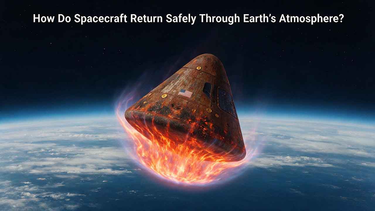
Spacecraft return safely through Earth’s atmosphere by following a precisely targeted trajectory, keeping a heat shield pointed into the hypersonic airflow, and using atmospheric drag to remove most of their kinetic energy. Guidance limits heating, structural loads, and landing error. Parachutes, wings, airbags, landing rockets, or water impact then manage the final descent and recovery.
Key Takeaways
- Safe atmospheric entry is an energy-management problem, not simply a controlled fall.
- A spacecraft must enter within a mission-specific corridor that limits heating, deceleration, structural loads, and landing error.
- A blunt shape and thermal protection system help keep extreme external heating away from the pressure vessel and crew.
- Atmospheric drag removes most of the spacecraft’s speed before parachutes or other terminal landing systems can operate.
- A safe return includes landing, flotation or surface stability, crew extraction, and postflight inspection—not just surviving peak heating.
This article explains the complete entry, descent, landing, and recovery sequence. It also compares low-Earth-orbit and lunar returns, shows how much kinetic energy must be managed, and introduces an editorial framework for understanding how trajectory, protection, control, and recovery work together.
On this page
How Do Spacecraft Return Safely Step by Step?
A spacecraft returns through Earth’s atmosphere through a sequence of linked events:
- Mission teams confirm the landing region and recovery conditions.
- The spacecraft targets an atmospheric-entry path or performs a deorbit burn.
- Modules not designed to survive reentry are separated at the planned time.
- The return vehicle points its primary heat shield into the airflow.
- The spacecraft reaches the atmosphere within its approved entry corridor.
- Atmospheric drag and controlled lift reduce speed.
- The thermal protection system limits heat transfer into the structure.
- Guidance and control systems manage attitude, range, and deceleration.
- Parachutes, wings, airbags, landing rockets, or another terminal system complete the descent.
- Recovery teams locate, stabilize, inspect, and access the vehicle.
These events are interdependent. A strong heat shield cannot compensate for a seriously incorrect trajectory, and an accurate trajectory cannot compensate for an unstable vehicle or a descent system operating outside its qualified conditions.
Generalized Capsule-Return Sequence
Atmospheric entry → Peak heating → Peak deceleration → Drogue deployment → Main parachutes → Landing or splashdown → Recovery
| Phase | Primary challenge | Main systems |
|---|---|---|
| Return targeting | Reaching the correct entry point and velocity | Navigation, propulsion, mission planning |
| Hypersonic entry | Managing heating, stability, and range | Heat shield, guidance, aerodynamic shape |
| Deceleration | Keeping structural and crew loads within limits | Trajectory design, structure, guidance |
| Parachute descent | Stabilizing the capsule and reducing terminal speed | Drogue and main parachutes |
| Landing and recovery | Protecting and reaching the crew after contact | Flotation, impact protection, recovery teams |
This original editorial sequence map shows a generalized capsule return. Exact event order, timing, altitude, and velocity vary by spacecraft.
Peak heating, peak dynamic pressure, and peak deceleration do not necessarily occur at the same time. Velocity falls as atmospheric density rises, so engineers must evaluate the entire trajectory rather than design around one maximum number.
How Is a Safe Return Opportunity Chosen?
A crewed spacecraft cannot normally begin its return at an arbitrary time.
For a low-Earth-orbit mission, the spacecraft must reach the correct orbital position before its deorbit maneuver. Mission teams also evaluate the landing footprint, available alternate sites, winds, storms, sea state, visibility, recovery assets, and spacecraft health.
Typical return criteria include:
- Orbital position and navigation accuracy
- Available propulsion and electrical power
- Cabin pressure and life-support status
- Winds at different altitudes
- Sea state or ground conditions
- Thunderstorms and visibility
- Recovery ship, aircraft, or ground-team readiness
- Availability of alternate landing regions
A lunar-return spacecraft follows a different pattern. It is already approaching Earth on a high-energy trajectory, so navigation teams use trajectory-correction maneuvers to target the required entry location, velocity, heading, and flight-path angle.
The return decision therefore connects orbital mechanics with practical recovery conditions. A thermally survivable trajectory may still be unacceptable if it leads to severe weather, rough seas, inaccessible terrain, or a region outside recovery coverage.
How Does a Deorbit Burn Start the Return?
A spacecraft in low Earth orbit is continuously falling around Earth. It remains in orbit because its sideways velocity carries it around the planet as Earth’s surface curves away beneath it.
A deorbit burn is a controlled engine firing that reduces orbital velocity enough for the spacecraft’s future path to intersect denser layers of the atmosphere.
The burn does not stop the spacecraft. It lowers the trajectory so that atmospheric drag can begin removing energy.
Propulsion hardware is normally retained until its final required task is complete. During Boeing Starliner’s uncrewed return on September 6, 2024, the spacecraft completed its deorbit burn before separating its expendable service module about two and a half minutes later. The service module had provided propulsion and power leading up to the maneuver, according to NASA’s Starliner return update.
This sequence illustrates a broader spacecraft-design principle: hardware should not be discarded until its final required function has been completed.
Why Must the Spacecraft Reconfigure Before Entry?
Many crewed spacecraft consist of several modules, but only the return module is designed to survive atmospheric entry.
Before reaching dense air, the spacecraft may need to:
- Secure the crew and loose equipment
- Close and verify pressure hatches
- Switch from external power to internal batteries
- Separate a service, orbital, or cargo module
- Configure cabin cooling and life support
- Activate entry navigation software
- Arm parachute and landing systems
- Point the primary heat shield into the airflow
The order matters. Separating a service module too early could remove propulsion, power, communications, or thermal-control capabilities before they are no longer needed. Separating it too late could disturb the return vehicle or expose attached structures to forces and heating they were not designed to withstand.
The spacecraft initially uses reaction-control thrusters to establish the required orientation. As the atmosphere becomes denser, the vehicle’s aerodynamic shape and control surfaces may provide increasing control authority.
During this phase, attitude-control sensors and actuators keep the heat shield and vehicle axes aligned with the required entry attitude until aerodynamic forces provide enough control authority.
Why Do Reentry Capsules Have Blunt Heat Shields?
A broad, rounded entry surface creates a detached shock wave ahead of the spacecraft.
Gas passing through the shock is strongly compressed and heated. Because the shock stands away from the surface, part of the hottest flow remains separated from the spacecraft structure.
NASA describes blunt-body entry vehicles as creating shock waves that help deflect extreme heating away from the main structure. The same general principle was demonstrated by NASA’s Low-Earth Orbit Flight Test of an Inflatable Decelerator.
A sharper nose can concentrate severe heating over a smaller region. That does not make every slender hypersonic vehicle impractical, but it creates a different thermal and structural challenge.
For many compact crew-return missions, a blunt capsule provides a useful combination of drag, stability, internal volume, and manageable heat-shield area.
Why Does Atmospheric Entry Become So Hot?
The most useful simple explanation is that the spacecraft creates a powerful shock wave and rapidly compresses the gas in front of it.
Reentry heating is not caused only by ordinary surface friction. Gas in the shock layer reaches very high temperatures, undergoes chemical reactions, and may become partly ionized. Energy then reaches the spacecraft through convection and, in sufficiently severe conditions, thermal radiation.
The heating environment depends on:
- Entry velocity
- Atmospheric density
- Vehicle shape and size
- Flight-path angle
- Angle of attack
- Surface condition
- Boundary-layer behavior
- Exposure time
- Atmospheric composition
- Material ablation and gas release
NASA’s Entry Systems overview explains how engineers combine aerothermodynamics, material response, testing, and computer modeling to evaluate these conditions.
Heating Rate and Total Heat Load Are Different
Heating rate, often expressed as heat flux, describes how quickly thermal energy reaches a unit of surface area.
Total heat load describes the accumulated thermal energy over the entire exposure period.
A relatively steep entry may produce a high heating rate over a shorter time. A shallower entry may reduce some peak values but keep the vehicle in the heating environment longer.
Neither condition is automatically safer. The trajectory must remain compatible with the heat-shield material, internal temperature limits, structural loads, guidance authority, and landing target.
How Much Energy Must a Returning Spacecraft Lose?
Kinetic energy provides a useful first estimate:
Kinetic energy = 0.5 × mass × velocity²
Illustrative Low-Earth-Orbit Calculation
Assume an illustrative return vehicle has:
- Mass: 10,000 kilograms
- Velocity: 7,800 meters per second
The calculation is:
Kinetic energy = 0.5 × 10,000 × 7,800²
Kinetic energy ≈ 3.04 × 10¹¹ joules
Kinetic energy ≈ 304 gigajoules
The spacecraft therefore carries approximately 304 gigajoules of kinetic energy in this simplified example.
The heat shield does not absorb all of this energy. Much of it is transferred into the atmosphere, shock layer, wake, sound, and motion of the surrounding gas.
The calculation also does not model the complete atmospheric-entry energy balance. It excludes factors such as changing gravitational potential, atmospheric rotation, lift, detailed trajectory effects, and local heat-flow distribution.
Values are rounded to three significant figures. The speeds are representative comparison values, not fixed specifications for every spacecraft.
The calculation also shows why atmospheric drag is essential: carrying enough propellant to remove the full return velocity propulsively would impose a very large mass penalty.
How Does a Lunar Return Compare With a Low-Earth-Orbit Return?
Kinetic energy per kilogram is proportional to velocity squared.
At an illustrative low-Earth-orbit return velocity of 7,800 meters per second:
Kinetic energy per kilogram ≈ 30.4 megajoules per kilogram
At an illustrative lunar-return velocity of 11,000 meters per second:
Kinetic energy per kilogram ≈ 60.5 megajoules per kilogram
The ratio is:
60.5 ÷ 30.4 ≈ 1.99
| Illustrative return case | Representative velocity | Kinetic energy per kilogram |
|---|---|---|
| Low-Earth-orbit return | 7.8 km/s | 30.4 MJ/kg |
| Lunar-distance return | 11.0 km/s | 60.5 MJ/kg |
For these representative velocities, the lunar-return example carries almost twice as much kinetic energy per kilogram.
For otherwise comparable Earth-entry vehicles, this generally makes a lunar return more demanding. However, the energy ratio alone cannot determine peak heat flux, heat-shield thickness, material recession, structural loads, or crew risk.
How Does a Heat Shield Protect the Spacecraft?
A thermal protection system, or TPS, limits the heat reaching the spacecraft’s structure, pressure vessel, wiring, tanks, computers, life-support equipment, and crew cabin.
The appropriate system depends on entry velocity, vehicle shape, expected reuse, allowable mass, manufacturing method, inspection access, and acceptable maintenance burden.
Outside atmospheric entry, spacecraft temperature is managed by a wider thermal-control system using insulation, conductive paths, heaters, heat exchangers, coolant loops, and radiators; the entry TPS is designed for a much shorter and more intense heating environment.
How Do Ablative Heat Shields Work?
An ablative heat shield uses material that chars, decomposes, releases gases, and gradually recedes in a controlled way.
These physical and chemical changes consume or redirect thermal energy. The remaining char layer also insulates the structure beneath it.
Ablation is not uncontrolled burning. Engineers qualify the material so that its recession, gas release, cracking behavior, thermal conductivity, and attachment remain predictable within the approved entry environment.
Ablative systems are well suited to compact capsules and high-energy returns. Their primary tradeoff is that consumed or altered material normally requires replacement, detailed inspection, or substantial refurbishment.
How Do Reusable Tiles and Hot Structures Work?
Reusable thermal protection may use ceramic tiles, insulating blankets, reinforced carbon-carbon, ceramic-matrix composites, or structures designed to tolerate high surface temperatures.
The Space Shuttle used different materials in different areas because heating was not uniform. NASA’s history of the Shuttle thermal protection system describes reusable silica-based tiles, while reinforced carbon-carbon protected especially hot nose and wing-leading-edge areas.
ESA’s Space Rider uses reusable ceramic protection on areas exposed to severe reentry heating. ESA has published details of plasma-wind-tunnel tests of Space Rider’s ceramic tiles and flap structures.
Which Heat-Shield Approach Is Better?
No thermal protection approach is best for every spacecraft.
| Protection approach | Main advantage | Main tradeoff |
|---|---|---|
| Ablative material | Handles severe heating by consuming material in a controlled way | Usually requires replacement or major refurbishment |
| Reusable ceramic tiles | Limits heat conduction and may support repeated flights | Damage-sensitive and inspection-intensive |
| Reinforced hot structures | Carries load while tolerating high surface temperature | Complex materials, coatings, joints, and manufacturing |
| Flexible or inflatable aeroshell | Creates a large drag area from a compact launch package | Deployment, stability, packing, and qualification challenges |
Thermal protection is an architecture decision rather than a simple contest between materials.
Engineers must consider entry energy, flight frequency, inspection access, manufacturing consistency, mass, cost, and the consequences of local damage.
How Does the Entry Corridor Protect the Spacecraft?
The entry corridor is the mission-approved range of entry conditions that keeps heating, deceleration, stability, range, and landing error within acceptable limits.
The corridor may be defined using combinations of:
- Entry location
- Velocity
- Flight-path angle
- Heading
- Vehicle attitude
- Atmospheric assumptions
- Guidance capability
- Landing-site geometry
| Entry condition | Possible consequence | Main concern |
|---|---|---|
| Shallower than planned | Longer flight, excessive range, prolonged heating, or an unintended skip | The vehicle does not reach dense air quickly enough |
| Within the approved corridor | Heating, loads, stability, and range remain manageable | The trajectory matches the analyzed entry case |
| Steeper than planned | Rapid deceleration, concentrated heating, and less correction time | The spacecraft reaches dense air while retaining excessive speed |
| Incorrect bank or attitude | Off-target flight, uneven heating, or instability | Aerodynamic forces no longer match guidance assumptions |
A shallow trajectory is not always an error. A lifting spacecraft may intentionally perform a skip entry, climbing after its first atmospheric pass before descending again.
The important distinction is whether the maneuver was planned, modeled, tested, and executed within the vehicle’s approved capability.
How Do Guidance and Control Systems Manage Reentry?
Many capsules generate a modest amount of lift because their center of mass is offset from their geometric center or because they fly at a selected angle of attack.
By rolling or banking the capsule, the guidance system changes the direction of that lift. This helps manage:
- Downrange distance
- Crossrange movement
- Descent rate
- Heating history
- Deceleration history
- Landing-location accuracy
Navigation Estimates the Spacecraft’s State
Navigation software estimates the spacecraft’s:
- Position
- Velocity
- Attitude
- Rotation rate
- Acceleration
- Predicted landing point
Inputs may come from inertial measurement units, accelerometers, gyroscopes, satellite-navigation receivers, pressure measurements, radar, radio tracking, or stored atmospheric models.
A reference atmosphere is not a perfect forecast of the real atmosphere. The official U.S. Standard Atmosphere, 1976 — NOAA Publication Directory is an idealized engineering model. Actual atmospheric density varies with location, season, weather, solar activity, and upper-atmospheric conditions.
Guidance software therefore compares measured vehicle behavior with predicted behavior and updates commands within the available control authority.
Control Systems Carry Out the Commands
In very thin air, aerodynamic control surfaces may have little authority. Reaction-control thrusters can establish or adjust attitude during the early entry phase.
As atmospheric density increases, control may come from:
- Capsule bank angle
- Body flaps
- Elevons
- Rudders
- Reaction-control thrusters
- A combination of thrusters and aerodynamic surfaces
The transition between control methods must be managed carefully because aerodynamic behavior changes as the vehicle passes from hypersonic through supersonic, transonic, and subsonic flight.
Why Can Communications Be Interrupted During Reentry?
The shocked gas around a fast-moving spacecraft can become partly ionized, forming plasma.
When electron density becomes high enough, the plasma can attenuate, reflect, or distort radio signals. The resulting communications interruption is commonly called reentry blackout.
Blackout is not identical for every spacecraft. It depends on:
- Entry speed and trajectory
- Plasma density
- Antenna location
- Radio frequency
- Vehicle geometry
- Signal path
- Relay availability
NASA studies these effects through research such as the NASA — Artemis II Re-entry Plasma Communications Blackout.
A temporary communications interruption does not mean the spacecraft has stopped operating. Entry guidance, navigation, control, fault management, and data recording continue onboard.
Communication performance during entry depends on antenna placement, vehicle attitude, plasma conditions, relay geometry, ground-station visibility, and onboard data storage for periods when a live link is unavailable.
How Does the Spacecraft Slow Down for Landing?
Atmospheric drag removes most of the spacecraft’s initial speed. Parachutes cannot normally open while a crew capsule is still traveling at hypersonic or high-supersonic velocity.
The vehicle first passes through several changing flow regimes:
- Hypersonic
- Supersonic
- Transonic
- Subsonic
- Terminal descent
The exact sequence varies by spacecraft.
What Do Drogue Parachutes Do?
Drogue parachutes are smaller parachutes used to stabilize the vehicle and reduce speed before the main parachutes open.
They help limit rotation, oscillation, and unfavorable attitude. Deploying a large main canopy while the capsule is moving too fast or tumbling could overload the parachute, attachment structure, or spacecraft.
What Do Main Parachutes Do?
Main parachutes provide the large drag area required for terminal descent.
They normally inflate in stages so they do not produce a single destructive opening shock. Reefing or staged deployment initially limits canopy expansion before allowing full inflation.
NASA’s Orion parachute system fact sheet states that Orion’s system is designed to tolerate the failure of one drogue parachute or one main parachute.
Parachute reliability is developed through repeated analysis, drop testing, imagery, inspection, and qualification. NASA’s SCIFLI team reports that it observed more than 40 separate SpaceX crew and cargo Dragon parachute-system tests between 2017 and 2020.
How Do Winged Vehicles Land?
A winged spacecraft uses aerodynamic lift to fly toward a runway or another prepared landing area.
This architecture may provide:
- Greater crossrange capability
- Runway recovery
- Convenient access to returned cargo
- Potential vehicle reuse
The tradeoff is additional mass and complexity from wings, control surfaces, landing gear, and distributed thermal protection.
A winged vehicle may become attractive when runway recovery, crossrange, cargo handling, or operational reuse justifies the added mass and thermal-protection complexity.
How Do Land-Landing Capsules Reduce Impact?
A land-landing capsule may combine parachutes with:
- Crushable structures
- Energy-absorbing seats
- Airbags
- Landing rockets
- Deformable landing systems
ESA describes Soyuz as using parachutes, shock-absorbing seats, and soft-landing engines fired shortly before ground contact.
An ocean-landing capsule instead relies on parachutes and a structure designed for water impact. It must then remain stable, watertight, ventilated, and accessible while awaiting recovery.
Which Landing Architecture Is Best?
No landing method is best for every mission.
| Landing architecture | Advantages | Tradeoffs |
|---|---|---|
| Parachute-assisted splashdown | Large potential landing regions and no runway requirement | Maritime recovery, sea-state exposure, and saltwater contamination |
| Parachute-assisted land landing | Avoids seawater and can place teams near the landing zone | Requires suitable terrain and impact attenuation |
| Runway landing | Controlled ground access and aircraft-like recovery | Adds wings, landing gear, TPS area, and runway constraints |
| Parachutes plus landing rockets | Reduces final ground-contact speed | Adds propulsion hardware, sensors, propellant, and timing requirements |
| Fully propulsive landing | May provide precise landing and rapid recovery | Requires substantial propellant and highly reliable propulsion and control |
For many compact crew-return missions, a capsule provides an efficient pressure structure with a manageable heat-shield area.
A winged or propulsive design may be justified when its operational advantages outweigh the additional mass, complexity, inspection burden, and failure modes.
The CosmoBasics Four-Layer Reentry Framework
The framework below is an editorial synthesis created for this article. It is not a NASA certification standard, flight rule, or substitute for a vehicle-specific safety assessment.
It organizes the return problem around four practical questions:
| Layer | Reader’s question |
|---|---|
| Path | Is the spacecraft entering at the right place, speed, and angle? |
| Protection | Can the structure and crew survive the environment? |
| Control | Can the vehicle remain stable and correct its trajectory? |
| Descent and Recovery | Can it land and continue supporting the crew afterward? |
Layer 1: Path
The spacecraft must reach an acceptable entry location, velocity, heading, and flight-path angle.
Useful questions include:
- Was the return maneuver completed accurately?
- Does the predicted path remain inside the entry corridor?
- Can guidance reach the primary or alternate landing region?
- Are weather and recovery conditions acceptable?
Layer 2: Protection
The vehicle must survive heating, pressure, vibration, deceleration, and landing loads.
Useful questions include:
- Is the thermal protection system in acceptable condition?
- Will the heat shield remain correctly oriented?
- Are structural and internal temperature limits protected?
- Are windows, seals, hatches, antennas, and penetrations adequately shielded?
Layer 3: Control
The spacecraft must remain stable and able to follow guidance commands.
Useful questions include:
- Do independent navigation measurements agree?
- Are thrusters or aerodynamic controls available?
- Can the vehicle manage bank angle and landing range?
- Is a validated backup or reduced-capability mode available?
Layer 4: Descent and Recovery
The spacecraft must transition from high-speed flight to a survivable landing and protect the crew afterward.
Useful questions include:
- Are parachute or landing-system deployment conditions valid?
- Are landing gear, airbags, flotation, or landing rockets ready?
- Can recovery teams locate and approach the vehicle?
- Can the crew remain safe if recovery is delayed?
The framework highlights an easily overlooked point: surviving peak heating is necessary, but it is not the end of the safety problem.
What Did Artemis I and Artemis II Teach Engineers?
NASA’s Orion missions provide a useful comparison because they show how uncrewed testing, postflight investigation, design changes, and a later crewed return fit together.
Artemis I: A Safe Landing With an Unexpected Heat-Shield Finding
The uncrewed Artemis I mission returned Orion from lunar distance in December 2022.
Orion approached Earth at approximately 25,000 mph and used a guided skip entry. The capsule entered the upper atmosphere, used drag to reduce speed, generated lift to climb again, and then completed its final descent toward the Pacific recovery area.
NASA describes the skip-entry trajectory and the later material investigation in its Artemis I heat-shield findings.
The atmosphere slowed Orion to approximately 300 mph before the parachute sequence. The parachutes then reduced its speed to about 20 mph before splashdown, according to NASA’s Orion recovery overview.
Orion landed safely, but postflight inspection found that charred Avcoat material had separated from the heat shield in more locations and in a different way than engineers had expected.
NASA concluded that gases generated inside portions of the ablative material could not vent and dissipate as expected. Pressure accumulated inside the material, contributing to cracking and the release of charred pieces.
The cabin environment remained within its required limits, but the unexpected material response required extensive testing, modeling, sampling, and review.
The broader lesson is important: a successful landing does not prove that every component behaved exactly as predicted. Recovered hardware and flight data must still be examined for unexpected damage and differences between models and real flight.
2026 Update: What Artemis II Added
Artemis II became Orion’s first crewed mission around the Moon.
NASA astronauts Reid Wiseman, Victor Glover, and Christina Koch, together with Canadian Space Agency astronaut Jeremy Hansen, returned safely on April 10, 2026, after a nearly 10-day mission.
Orion completed a parachute-assisted splashdown in the Pacific Ocean off the coast of San Diego. NASA documented the return in its Artemis II crew splashdown announcement.
NASA’s initial postflight assessment reported that:
- Orion’s thermal protection system performed as expected.
- Initial inspections found no unusual thermal-protection conditions.
- The char-loss behavior observed on Artemis I was significantly reduced in both quantity and size.
- Entry-interface velocity was within one mile per hour of the predicted value.
- Orion splashed down 2.9 miles from its targeted landing point.
These details come from NASA’s initial Artemis II spacecraft assessment.
The word initial matters. NASA also planned additional de-servicing, sample extraction, imagery analysis, internal X-ray scans, and review of postflight data.
The early findings therefore support confidence in the mission’s performance, but they should not be described as proof that every heat-shield question has been permanently resolved.
Status note: This section reflects NASA information available as of August 1, 2026. It should be updated if NASA’s later postflight heat-shield analysis materially changes the preliminary findings.
What Happens When Part of the Return Is Off-Nominal?
The following table explains engineering concerns and design responses. It is not an operational procedure for any spacecraft or crew.
| Off-nominal condition | Main concern | System-level response |
|---|---|---|
| Incomplete deorbit burn | Incorrect entry point or landing footprint | Determine the achieved velocity change and evaluate approved alternatives |
| Steeper-than-planned entry | Greater deceleration and concentrated heating | Use available guidance authority or a validated backup mode |
| Shallower-than-planned entry | Excessive range, prolonged heating, or unintended skip | Adjust lift direction within the qualified guidance envelope |
| Degraded attitude control | Heat shield may not remain correctly oriented | Use redundant sensors, thrusters, control modes, or passive stability |
| Navigation disagreement | Guidance may act on an incorrect state estimate | Compare independent measurements and apply validated fault logic |
| Communications interruption | Ground teams temporarily lose telemetry or commands | Continue autonomous onboard guidance and stored procedures |
| Parachute failure | Reduced stability or higher landing speed | Use qualified redundancy and failure-tolerant landing systems |
| Landing-zone deterioration | Unsafe landing or recovery conditions | Delay return when possible or use an approved alternate region |
| Unstable post-landing orientation | Reduced ventilation, communication, or crew access | Use flotation and uprighting systems while recovery teams approach |
The safest response is usually not improvised during the event. It is designed, analyzed, simulated, tested, and incorporated into flight rules long before launch.
What Must Be Confirmed Before a Crewed Return?
A high-level, vehicle-independent readiness checklist includes:
- The primary and alternate landing regions are acceptable.
- Weather, winds, waves, visibility, and surface conditions meet mission criteria.
- Independent navigation solutions agree within approved limits.
- Required return or deorbit propulsion is available.
- Guidance and attitude-control systems are healthy.
- The thermal protection system has no known disqualifying damage.
- Cabin pressure, life support, cooling, and internal power are ready.
- Module-separation systems are correctly configured.
- Seats, restraints, suits, and loose equipment are secured.
- Parachutes or other landing systems are armed as required.
- Communications, tracking, and recovery assets are positioned.
- Post-landing flotation, ventilation, hazard control, and extraction systems are ready.
This educational checklist cannot replace certified flight rules, manufacturer procedures, or mission-specific crew checklists.
Cabin protection during return also depends on pressure control, oxygen supply, carbon dioxide removal, ventilation, temperature and humidity control, fire protection, and the ability to manage post-landing hazards until recovery.
“Reentry Heat Is Only Friction”
Surface interactions contribute to heating, but the extreme environment is primarily associated with shock formation, rapid gas compression, chemical reactions, and heat transfer from the surrounding flow.
“The Heat Shield Alone Makes Reentry Safe”
A heat shield cannot correct an invalid trajectory, major attitude error, unstable vehicle, failed structure, or unusable landing system. Safe return requires the complete system.
“Parachutes Slow the Spacecraft From Orbital Speed”
Atmospheric drag removes nearly all orbital velocity first. Parachutes deploy only after the capsule reaches acceptable speed, altitude, attitude, and dynamic-pressure conditions.
“The Spacecraft Falls Straight Down”
A returning spacecraft initially travels mostly sideways around Earth. Its trajectory curves downward as drag removes horizontal velocity and gravity changes its path.
“A Shallower Entry Is Always Safer”
A shallower path may reduce certain peak loads, but it can increase downrange travel, total heat exposure, and the possibility of an unintended skip.
“Splashdown Ends the Risk”
After landing, crews may still face rough seas, leaks, fire, hazardous residues, unstable flotation, damaged antennas, or delayed extraction. Recovery is part of return safety.
How Are Reentry Systems Tested?
No single test reproduces every aspect of atmospheric entry. Engineers combine several forms of evidence.
Computer Modeling
Models predict:
- Aerodynamic forces
- Shock-layer chemistry
- Convective and radiative heating
- Ablation and material recession
- Structural temperatures and loads
- Guidance performance
- Parachute inflation
- Landing dynamics
NASA’s Entry Systems Modeling project develops tools for predicting entry environments and vehicle response.
Arc-Jet Testing
Arc-jet facilities expose thermal-protection samples to high-energy gas flows.
Engineers compare measured recession, temperatures, cracking, and gas behavior with computational predictions. An arc-jet test can reproduce important parts of the heating environment, but no single test perfectly recreates every pressure, duration, chemistry, and trajectory condition.
Wind-Tunnel and Aerodynamic Testing
Wind tunnels and other aerodynamic facilities help evaluate:
- Shock-wave shape
- Stability
- Control authority
- Surface pressure
- Boundary-layer transition
- Vehicle response to roughness or damage
Drop Testing
Parachutes, airbags, landing rockets, seats, and impact structures can be tested with instrumented capsules or representative test articles.
Drop tests allow engineers to study deployment failures, oscillation, canopy loading, impact orientation, and redundancy without requiring a complete orbital mission.
Uncrewed Integrated Flight Tests
An uncrewed flight reveals interactions that isolated component tests may miss.
Artemis I tested Orion’s heat shield, skip-entry guidance, parachutes, splashdown systems, and recovery sequence before astronauts flew on Artemis II.
Postflight Inspection
Recovered hardware can reveal:
- Material recession
- Cracks or voids
- Missing char or tiles
- Seal performance
- Parachute loading
- Structural deformation
- Unexpected heating paths
- Differences between prediction and flight
Postflight evidence feeds back into material production, inspection criteria, software, simulations, and future mission rules.
What This Article Does Not Claim
This article does not claim that every spacecraft follows the same entry sequence or encounters the same temperatures, g-loads, blackout period, or parachute conditions.
Actual results depend on the vehicle’s:
- Entry velocity
- Mass and shape
- Trajectory
- Lift-to-drag ratio
- Thermal protection
- Atmospheric conditions
- Guidance strategy
- Landing architecture
- Hardware condition
- Mission origin
The calculations in this article are educational examples, not heat-shield design tools. They do not predict local heat flux, material recession, structural margin, or crew risk.
What Should Readers Take Away?
A safe spacecraft return is a controlled chain of events.
The spacecraft must reach the correct entry path, survive heating, remain stable and steerable, slow through several aerodynamic regimes, and complete a recoverable landing. Weakness in one part of the chain can affect every part that follows.
General readers can use the four-layer framework to compare different return systems. Engineering students should treat the energy calculation as a starting point before studying heat transfer, atmospheric models, material response, trajectory optimization, and uncertainty. Mission operators must rely on certified vehicle-specific documentation and flight rules rather than simplified public explanations.
Why do spacecraft not use engines to slow down from orbital speed?
Removing the entire orbital velocity with engines would require a very large amount of propellant. Earth’s atmosphere provides most of the deceleration through drag. Engines may still be used for the deorbit burn, attitude control, trajectory corrections, or final landing.
Can astronauts manually steer during reentry?
Some spacecraft provide manual or backup control, but nominal reentry is highly automated. Guidance computers process navigation measurements and update commands rapidly as the atmosphere and vehicle behavior change.
Can a spacecraft skip back into space?
A shallow, lifting trajectory can cause a spacecraft to climb after an initial atmospheric pass. This may be unintended or part of a planned skip entry. A planned skip remains on an Earth-return trajectory and later reenters denser atmosphere.
Does every spacecraft experience a complete communications blackout?
No. Signal attenuation depends on plasma density, antenna placement, radio frequency, geometry, trajectory, and available relay paths. Some missions experience a substantial interruption, while others retain partial or intermittent communications.
Can a damaged heat shield be repaired in orbit?
Repair capability depends on the spacecraft design, damage location, tools, crew access, and mission plan. Many capsule heat shields are not practically accessible in space, making damage prevention, inspection, monitoring, and conservative return criteria especially important.
Is returning from the Moon harder than returning from low Earth orbit?
For otherwise comparable vehicles, a lunar return generally involves greater entry velocity and more kinetic energy per kilogram. The complete challenge still depends on trajectory, vehicle shape, heat-shield technology, structural limits, and mission requirements.
Additional Authoritative References
Entry Physics and Thermal Protection
- NASA Ames — Entry Systems
- NASA — Entry Systems Modeling: Aerothermodynamics, Guidance, and Vehicle Response
- NASA — LOFTID Blunt-Body Heat-Shield Demonstration
- NASA — Space Shuttle Thermal Protection System History
- ESA — Space Rider Ceramic Thermal-Protection Tests
- NOAA — U.S. Standard Atmosphere, 1976 Publication Directory
Guidance, Navigation, and Communications
- NASA — Orion’s Skip-Entry Technique
- NASA — Artemis I Orion Heat Shield and Skip-Entry Findings
- NASA — Artemis II Re-entry Plasma Communications Blackout
Parachutes, Landing, and Recovery
- NASA — Orion Parachute System (PDF)
- NASA SCIFLI — SpaceX Dragon Parachute Testing
- ESA — Soyuz Reentry and Soft-Landing Sequence
- NASA — Starliner Deorbit Burn and Service Module Separation
- NASA — Orion Landing and Recovery
Orion and Artemis Case Studies
- NASA — Artemis I Orion Heat-Shield Char-Loss Findings
- NASA — Artemis II Crew Return and Splashdown
- NASA — Initial Artemis II Spacecraft and Heat-Shield Assessments
How This Article Was Reviewed
This article was researched and fact-checked using the NASA, ESA, NOAA, and NASA Technical Reports Server sources listed above.
Mission-specific statements about Starliner, Dragon parachute testing, Soyuz landing, Artemis I, and Artemis II are linked to the corresponding agency pages. The 304-gigajoule example and the low-Earth-orbit versus lunar-return comparison are editorial calculations based on the kinetic-energy relationship shown in the article.
The CosmoBasics Four-Layer Reentry Framework is an editorial method for organizing established engineering considerations. It is not an agency standard, certification system, or flight rule.
AI-assisted editing was used to improve organization and readability. Factual claims, calculations, and source links were reviewed before publication. This page has not been independently reviewed by a spacecraft engineer and does not claim endorsement by NASA, ESA, NOAA, a spacecraft manufacturer, or a mission operator.
Readers can report factual or link errors through the site’s contact page. Mission-status sections are reviewed when the relevant agencies publish material new findings.
More from Human Spaceflight
How Do Astronauts Sleep, Eat, and Exercise in Space?
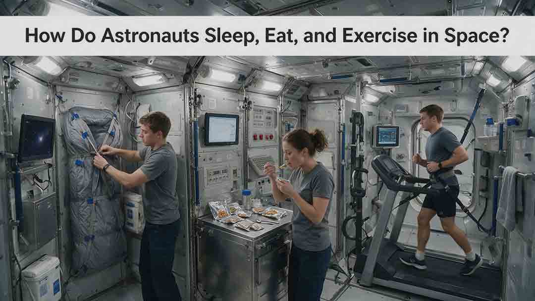
Astronauts must redesign ordinary routines when they live in microgravity. This article explains how crew members sleep in secured bags inside ventilated quarters, prepare packaged meals without letting food or liquids drift through the cabin, and use specialized exercise equipment to protect their physical condition. It examines the roles of the Advanced Resistive Exercise Device, the T2 treadmill, and the CEVIS cycle ergometer, while clarifying the difference between active workout time and the full scheduled exercise period. Readers will also learn why tortillas are practical in space, how airflow affects sleep, why ordinary weights do not work normally in orbit, and how nutrition, rest, and exercise support one another. NASA and ESA sources provide the factual foundation, while original comparison tables and practical evaluation frameworks show how spacecraft systems replace functions normally supplied by gravity. The article also distinguishes current International Space Station practices from possible future Moon and Mars mission requirements.
What Happens to the Human Body in Microgravity?
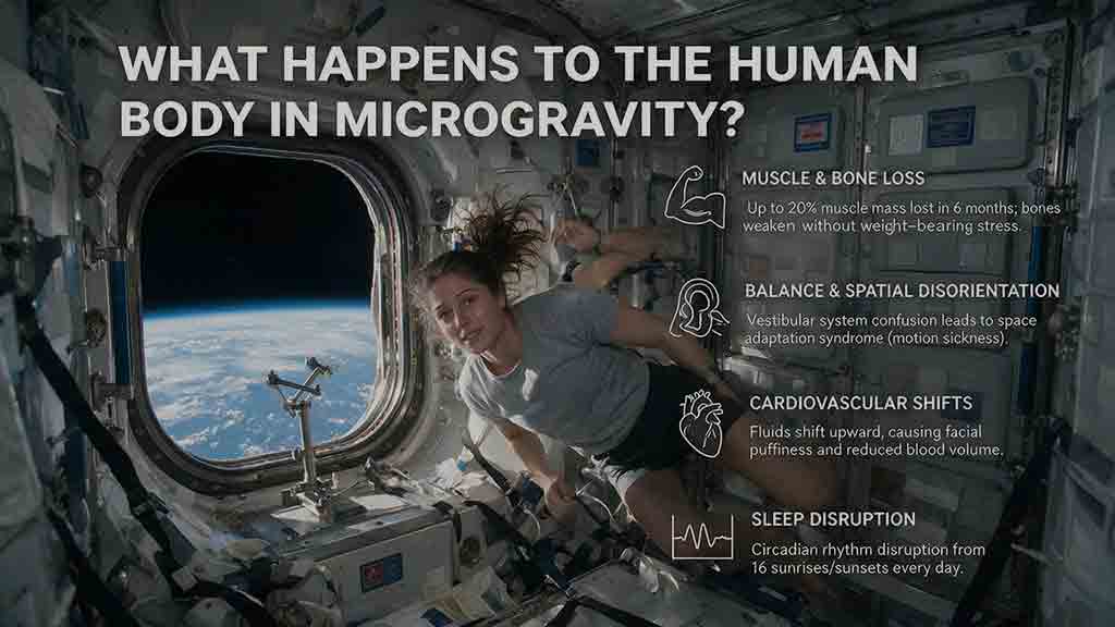
Microgravity changes the human body because fluids are no longer pulled toward the legs, muscles and bones receive less mechanical loading, and the brain loses gravity as a dependable orientation signal. This article explains how weightlessness affects balance, circulation, muscle strength, bone density, vision, blood, immunity, digestion, sleep, and spinal length. It also examines why astronauts may struggle to stand or walk after landing and how exercise, nutrition, monitoring, and rehabilitation help reduce these risks. Two original tools—the Load–Flow–Orientation Framework and the Gravity-Transition Readiness Matrix—connect physiological changes with real mission demands. Drawing on NASA standards, NASA technical reports, ESA materials, and peer-reviewed human spaceflight research, the guide clearly separates established observations from experimental countermeasures and unresolved questions. It also explains what these effects could mean for future missions to the Moon and Mars without treating population averages as predictions for individual astronauts.

How Does a Spacecraft Life Support System Work?
A spacecraft life support system creates and maintains a safe cabin environment for astronauts by managing oxygen, carbon dioxide, air pressure, ventilation, temperature, humidity, water, waste, and environmental hazards. This article explains how the Environmental Control and Life Support System connects these functions into continuous air, water, heat, and waste-management loops. It compares stored-resource and regenerative designs, examines how the International Space Station and Orion use different life support architectures, and clarifies what NASA’s reported 98% water-recovery milestone actually means. Readers will also find an educational water-use calculation, a high-level architecture checklist, a system-failure comparison table, and the original Four-C framework for evaluating Crew, Calendar, Cargo, and Consequences. The guide relies on NASA and European Space Agency sources while clearly separating official facts, illustrative estimates, and independent editorial analysis.
Explore More Topics
How Are Space Missions Planned From Design to Launch?
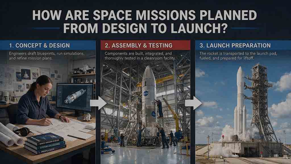
Space missions are planned by transforming a scientific, commercial, or exploration goal into a complete system that can be designed, built, tested, launched, operated, and responsibly concluded. This guide follows the full planning lifecycle, from defining measurable objectives and comparing mission concepts to writing requirements, selecting an architecture, managing resource budgets, and controlling interfaces. It explains how payloads, spacecraft platforms, trajectories, launch services, software, ground systems, regulations, and operations must be developed together. Readers will also learn how design reviews, fabrication, environmental testing, end-to-end verification, operator training, licensing, launch integration, and readiness assessments support mission development. Original planning frameworks, worked mass, power, and data calculations, troubleshooting guidance, and a practical checklist show how teams identify weak assumptions and resolve designs that do not close. The central lesson is that mission readiness depends on the entire technical and operational system—not merely on completing the spacecraft.
What Happens During a Rocket Launch Countdown?
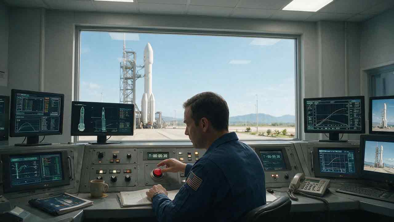
A rocket launch countdown is far more than a clock running toward zero. It is a carefully coordinated process that brings the launch vehicle, spacecraft, ground equipment, flight teams, weather conditions, and safety range into an approved configuration for liftoff. This article explains the major countdown phases, including launch-pad preparation, propellant loading, avionics and navigation checks, weather monitoring, range clearance, go/no-go polls, and terminal count. It also clarifies commonly misunderstood terms such as T-minus, L-minus, planned hold, recycle, scrub, and launch window. An original Four-C Countdown Framework—Clock, Configuration, Constraint, and Commitment—helps readers understand why teams may continue, pause, return to an earlier step, or cancel a launch attempt. Practical timelines, comparison tables, a launch-window calculation, and a viewer’s checklist make the article useful for students, educators, first-time launch viewers, and spaceflight enthusiasts.
How Do Spacecraft Dock in Orbit?
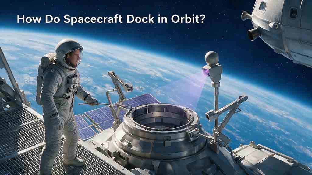
Spacecraft docking is a carefully controlled process that begins long before two vehicles make physical contact. The approaching spacecraft must first establish compatible orbital geometry, adjust its timing through phasing maneuvers, and reduce differences in position, velocity, and orientation. This guide explains the complete sequence from far-field rendezvous and relative navigation to hold points, final approach, soft capture, and hard capture. It also compares docking with robotic berthing, examines the sensors and control systems used during an approach, and shows how mission teams respond when navigation data, closing rates, or alignment fall outside permitted limits. A simplified orbital calculation demonstrates why a spacecraft in a slightly lower orbit can gradually catch its target. Readers will also find an original five-match framework, a practical docking-safety model, real mission examples, and a checklist for evaluating docking plans. The article clearly distinguishes educational principles from vehicle-specific flight procedures and engineering requirements.