How Are Space Missions Planned From Design to Launch?

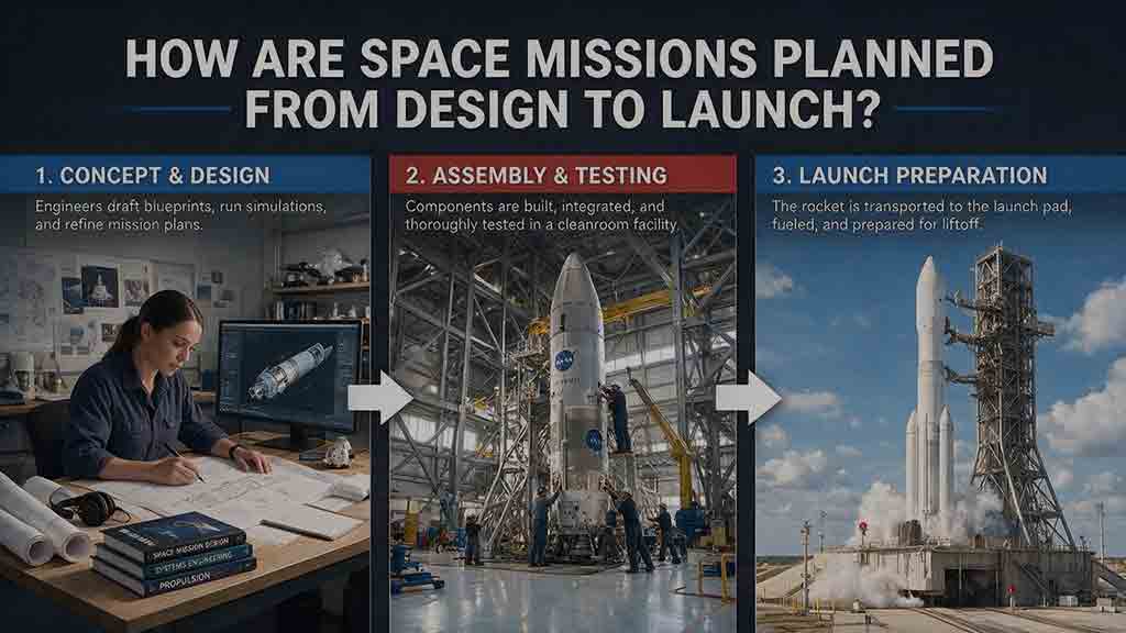
How Are Space Missions Planned From Design to Launch?
By helen
Space missions are planned by turning a scientific, commercial, or exploration goal into measurable requirements, comparing feasible architectures, designing the payload, spacecraft, trajectory, launch service, ground segment, and operations as one connected system, and then proving readiness through reviews, fabrication, testing, rehearsals, regulatory work, and final launch preparations.
Key Takeaways
- Mission planning begins with a result that users need, not with a preferred spacecraft, instrument, orbit, or rocket.
- The payload, spacecraft, trajectory, launch service, software, ground systems, and operations plan must be developed together.
- Mass, power, data, cost, schedule, and risk budgets must remain credible as the design matures.
- Formal reviews are evidence-based decision points, not guarantees that every technical risk has disappeared.
- A mission is ready only when its flight system, launch service, ground infrastructure, operators, procedures, approvals, and contingency plans are ready together.
Understanding how space missions are planned helps distinguish an attractive idea from a mission that can actually be built, launched, operated, and used. This guide follows that process from the first objective to launch readiness and includes two original planning frameworks, three worked calculations, a concept decision path, a troubleshooting guide, and a practical checklist.
In This Guide
- The complete mission lifecycle
- Defining the mission objective
- Comparing mission concepts
- Writing useful requirements
- Designing the connected architecture
- Closing mass, power, and data budgets
- Using design reviews
- Detailed design and fabrication
- Integration and testing
- Planning mission operations
- Licensing and mission responsibilities
- Selecting a launch service
- Preparing for launch
- Mars 2020 planning example
- Common mistakes and troubleshooting
- Mission-planning checklist
- FAQ
- Sources and editorial approach
How Are Space Missions Planned Across the Full Lifecycle?
A space mission is planned through an iterative lifecycle in which an initial goal becomes progressively more detailed, testable, and controlled.
Early teams investigate several possible solutions. Later teams select an architecture, establish requirements, complete the design, manufacture hardware, develop software, integrate the system, test it, train operators, and demonstrate launch readiness.
NASA organizes many spaceflight projects into Pre-Phase A followed by Phases A through F. ESA describes a related lifecycle beginning with Phase 0 and continuing through feasibility, preliminary definition, detailed definition, qualification and production, utilization, and disposal.
| Mission stage | Main question | Typical evidence |
|---|---|---|
| Need and early concept | Is there a valuable problem or opportunity? | Objectives, users, constraints, candidate concepts |
| Feasibility and architecture | Can a credible mission satisfy the objectives? | Trade studies, initial requirements, technology and risk plans |
| Preliminary design | Can the selected design work within available resources? | Subsystem designs, interfaces, budgets, verification plans |
| Detailed design and fabrication | Is the design mature enough to build and code? | Released drawings, controlled software, manufacturing records |
| Integration and qualification | Does the assembled system work and survive its expected environments? | Integrated tests, environmental tests, anomaly dispositions |
| Launch preparation | Are the flight and ground elements ready together? | Readiness evidence, procedures, rehearsals, certifications |
| Operations and closeout | Can the mission deliver its intended results and end responsibly? | Commissioning results, mission products, disposal activities |
Phase names, review names, entry criteria, and decision authorities vary by agency, company, contract, mission class, and project risk. The lifecycle above is a general map rather than a mandatory global standard.
NASA explains its approach in the NASA Program and Project Life Cycle. ESA provides a complementary overview in Building and Testing Spacecraft.
The Mission-Planning Lifecycle at a Glance
Mission objective → Concept studies → Requirements and architecture → Preliminary design → Detailed design and fabrication → Integration and testing → Launch preparation → Operations → Closeout or disposal
This original editorial summary shows the usual direction of development, but the process is not strictly one-way. Test findings can force design changes, new constraints can alter requirements, and launch or ground-system limitations can send a team back to its architecture study.
Step 1: How Does a Space Mission Begin?
A space mission begins with a need, opportunity, or objective that can be converted into measurable results. It should not begin with the assumption that a particular spacecraft or technology must be used.
“Build a satellite with a multispectral camera” is a proposed solution. “Provide recurring observations that help identify changes in coastal water conditions” is closer to a mission objective.
The Goal-to-Hardware Traceability Chain
A practical way to test an early mission idea is:
Goal → Observable → Measurement → Payload → Orbit or trajectory → Spacecraft services → Ground product
This Goal-to-Hardware Traceability Chain is an original editorial framework developed for this guide. Its purpose is to reveal missing connections before a team commits to hardware.
Consider a hypothetical mission intended to monitor harmful algal blooms:
- Goal: Improve awareness of bloom location and change.
- Observable: Spectral and color differences in coastal water.
- Measurement: Calibrated images in selected spectral bands.
- Payload: An imaging instrument with suitable sensitivity and resolution.
- Orbit: A path that provides useful lighting and revisit opportunities.
- Spacecraft services: Pointing, power, timing, thermal control, storage, and communications.
- Ground product: Processed maps delivered to researchers or public agencies.
Each link changes the next one. Greater image resolution can increase data volume and pointing demands. More frequent observations can change the orbit, storage, downlink schedule, and ground-processing workload.
If the team cannot explain how the proposed hardware produces a useful result for the original user, the concept is incomplete.
Which questions should be answered first?
An early mission team should identify:
- Who will use the mission’s results?
- What measurement, service, discovery, or decision should the mission enable?
- What would count as minimum success?
- What would count as full success?
- Where and when must the mission operate?
- How quickly must information reach users?
- Which environmental, financial, scheduling, safety, and regulatory constraints apply?
- Which assumption could invalidate the concept if it proves wrong?
Separating minimum success from full success gives the team a way to preserve the mission’s central value if funding, mass, schedule, or technology constraints force a reduction in scope.
Step 2: How Are Mission Concepts Compared?
Mission concepts are compared through documented trade studies rather than by selecting the most exciting design.
A useful trade study defines:
- The alternatives
- The decision criteria
- The evidence behind each estimate
- Important uncertainties
- Technical and programmatic risks
- The reason for choosing or rejecting each option
Possible alternatives include one large spacecraft versus several smaller spacecraft, a dedicated launch versus rideshare, a custom payload versus heritage hardware, or frequent ground commanding versus greater onboard autonomy.
The CLOSER Mission-Concept Test
The following six-part framework can reveal whether a concept is ready for deeper development.
C — Capability
Can the architecture produce the required measurement, service, or exploration result?
A warning sign is impressive hardware with no direct connection to a measurable mission objective.
L — Launch
Can a suitable launch service deliver the spacecraft to the required orbit or trajectory within mass, volume, interface, environmental, and scheduling constraints?
Fitting inside a payload fairing does not by itself establish launch compatibility.
O — Operations
Can operators communicate with, command, monitor, navigate, and use the spacecraft with realistic ground infrastructure and staffing?
The design is incomplete if it depends on unconfirmed ground access, contact time, data processing, or operator availability.
S — Schedule
Can technology, software, hardware, facilities, approvals, and personnel become ready in the required order?
A schedule is vulnerable when several critical activities depend on one immature component, unavailable facility, or fixed launch opportunity.
E — Economics
Can the complete lifecycle be supported?
A credible estimate may need to include design, fabrication, software, testing, launch integration, ground services, operations, data processing, anomaly response, and disposal—not just spacecraft construction.
R — Risk
Are major technical, operational, programmatic, safety, and external risks identified, assigned, and treated?
A plan that assumes every new element will work correctly on its first attempt has hidden risk rather than eliminated it.
CLOSER is an original editorial screening framework. It does not replace a project’s formal systems-engineering or risk-acceptance process.
Which architecture is better?
The table below shows common architecture choices. The preferred option depends on the mission rather than on a universal ranking.
| Decision | Option A | Option B | Central trade-off |
|---|---|---|---|
| Launch strategy | Dedicated launch | Rideshare | Greater control versus lower potential launch cost |
| Space segment | One spacecraft | Several spacecraft | Simpler operations versus coverage and resilience |
| Payload | Custom instrument | Heritage instrument | Optimized performance versus maturity |
| Data handling | Return raw data | Process data onboard | Ground flexibility versus communications demand |
| Operations | Frequent ground control | Greater autonomy | Direct control versus software complexity |
| Ground access | Owned stations | Network services | Infrastructure control versus geographic access |
A weighted score can help organize discussion, but it should not conceal a fatal constraint. A concept with no viable communications path cannot be rescued by strong scores in less critical categories.
A Quick Concept Decision Path
Can the objective be measured or otherwise verified?
If not, redefine the objective.Does at least one architecture connect the payload, trajectory, spacecraft, ground segment, and operations?
If not, broaden the concept study.Do preliminary mass, power, data, cost, and schedule budgets close?
If not, reduce scope or change the architecture.Can critical technology mature before it is needed?
If uncertain, conduct an early demonstration and identify a fallback.Is there a credible path for launch, communications, approvals, and end-of-mission responsibility?
If not, the mission is not ready to enter detailed development.
Step 3: How Do Objectives Become Requirements?
Objectives become requirements by translating desired results into statements that can be designed, verified, and traced.
A requirement should state what the system must accomplish under defined conditions. It should avoid prescribing a specific design unless that design is itself a genuine constraint.
What makes a requirement useful?
A useful requirement is:
- Necessary for an objective or constraint
- Clear enough to support one defensible interpretation
- Feasible within the architecture
- Verifiable by test, analysis, inspection, or demonstration
- Traceable to a stakeholder need
- Assigned to the responsible system element
- Controlled after it is baselined
NASA’s Requirements Management guidance emphasizes traceability among stakeholder expectations, technical requirements, design information, and verification work.
Weak requirement versus useful requirement
Weak statement:
The spacecraft should send data quickly.
This does not define the data, delivery point, time limit, operating conditions, or allowed exceptions.
More useful structure:
The ground segment shall deliver the defined mission data product within the specified latency after receipt under the approved operating conditions.
The actual latency must come from user needs and mission analysis. It should not be selected merely because a preferred radio or ground station can support it.
Why can one requirement affect several systems?
Increasing image resolution may affect:
- Payload aperture or detector design
- Pointing accuracy
- Structural stability
- Onboard processing
- Data storage
- Downlink capacity
- Electrical power
- Heat rejection
- Calibration effort
- Ground-processing cost
Requirement changes are therefore evaluated across the mission rather than treated as isolated improvements.
Step 4: How Are All Mission Elements Designed Together?
The payload, spacecraft, orbit, launch service, flight software, ground segment, and operations plan are developed together because no mission element works independently.
An orbit influences lighting, coverage, radiation, thermal cycling, communications, propulsion, and launch opportunities. A payload influences pointing, structural stiffness, data generation, power, and temperature.
NASA describes system design as an iterative relationship among stakeholder expectations, technical requirements, system functions, and design solutions in its System Design Processes guidance.
Which elements form the mission architecture?
| Element | Main planning question |
|---|---|
| Payload | What measurement, service, or activity creates mission value? |
| Orbit or trajectory | Where must the spacecraft travel or operate? |
| Spacecraft platform | What power, pointing, computing, thermal, propulsion, and structural services are needed? |
| Flight software | Which functions and fault responses must occur onboard? |
| Ground segment | How will commands, telemetry, tracking data, and mission products move? |
| Launch service | Which vehicles and interfaces are compatible? |
| Operations concept | How will people, software, facilities, and procedures operate the mission? |
| End-of-mission plan | How will the mission be concluded, passivated, disposed of, or closed out? |
The ground segment is not a late accessory. NASA’s Ground Data Systems and Mission Operations discusses ground stations, communications networks, control centers, software, frequency considerations, cybersecurity, and end-to-end testing as parts of the mission.
How the Main Mission Elements Connect
Mission objective defines what the payload must accomplish.
The orbit or trajectory determines where and when it can operate.
The spacecraft platform supplies power, pointing, computing, thermal control, propulsion, and communications.
Flight software coordinates onboard behavior and fault responses.
The ground segment commands the spacecraft and turns telemetry into useful products.
The launch service constrains mass, volume, loads, interfaces, and destination.
The operations plan determines how people and systems use the spacecraft throughout its life.
The closeout plan determines how the mission ends responsibly.
This is an original editorial relationship map, not an official NASA or ESA architecture diagram.
Which resource budgets must close?
Common planning budgets include:
- Mass and physical volume
- Electrical power and stored energy
- Payload data generation
- Onboard storage
- Communications capacity
- Propellant and maneuver capability
- Pointing accuracy and stability
- Thermal control
- Processor and memory use
- Cost
- Schedule
- Staffing and operating workload
- Risk and contingency reserves
A useful budget shows assumptions, current estimates, limits, uncertainty, operating modes, margin, and ownership. A single unlabeled number is not enough.
Worked Example: Can a Small Observation Mission Close?
The following example is hypothetical. It demonstrates planning logic and does not describe a real spacecraft, launch allocation, or recommended margin policy.
Example assumptions
| Assumption | Illustrative value |
|---|---|
| Current estimated spacecraft mass | 235 kg |
| Preliminary launch mass allocation | 300 kg |
| Illustrative mass margin | 20% |
| Highest planned electrical load | 450 W |
| Illustrative power margin | 25% |
| Payload data generated per day | 40 GB |
| Usable contacts per day | 4 |
| Usable duration of each contact | 8 minutes |
| Effective transfer utilization | 70% |
The data example uses decimal communications units:
- 1 GB = 8 Gb
- 40 GB = 320 Gb
Does the mass budget close?
Assume the current mass estimate contains:
| Item | Estimated mass |
|---|---|
| Spacecraft platform and structure | 165 kg |
| Payload | 42 kg |
| Propellant | 18 kg |
| Adapter, harness, and integration hardware | 10 kg |
| Current estimate | 235 kg |
Apply the illustrative 20% margin:
235 kg × 20% = 47 kg
Add the margin:
235 kg + 47 kg = 282 kg
Compare the result with the allocation:
300 kg − 282 kg = 18 kg remaining
The concept fits the preliminary allocation, but the small remaining allowance may be vulnerable to later growth.
The team should determine which values are measured, calculated, supplier-supported, or still uncertain. Deleting the margin from the spreadsheet would not remove the uncertainty.
Projects may define and apply margin differently according to subsystem maturity, development phase, mission class, and organizational policy. Margin, reserve, contingency, and remaining allocation are not always interchangeable terms.
Does the power budget close?
Assume these loads:
- Housekeeping systems: 150 W
- Imaging payload: 220 W
- High-rate downlink: 170 W
- Worst-case heater demand: 80 W
Operating every load simultaneously would require:
150 W + 220 W + 170 W + 80 W = 620 W
If imaging and high-rate downlink do not need to occur together, the highest planned operating mode may be:
150 W + 220 W + 80 W = 450 W
Apply the illustrative 25% margin:
450 W × 1.25 = 562.5 W
Operating modes can reduce peak demand, but the mission still requires analysis of eclipse periods, battery charging, degradation, transitions between modes, thermal conditions, and fault states.
As with the mass example, real projects may assign and manage power margin differently according to maturity and policy.
Can the mission return its daily data?
The payload generates 40 GB per day:
40 GB × 8 = 320 Gb
Four eight-minute contacts provide:
4 × 8 minutes × 60 seconds = 1,920 seconds
The useful transfer rate needed during contact is:
320 Gb ÷ 1,920 seconds ≈ 166.7 Mb/s
If only 70% of theoretical link capacity carries the required data:
166.7 Mb/s ÷ 0.70 ≈ 238.1 Mb/s
Under these assumptions, the communications architecture needs approximately 238 Mb/s of theoretical contact capacity.
If the selected radio or ground network cannot support that result, the team may need to:
- Reduce payload data generation
- Compress or process data onboard
- Increase contact duration
- Add ground stations
- Improve the communications system
- Store data for later transmission
- Accept greater latency
- Reduce observation volume
This simplified calculation estimates required data throughput; it is not a complete communications link budget. A real design must also evaluate range and geometry, antenna gain, transmitter power, propagation and atmospheric losses, modulation, coding, implementation losses, regulatory limits, ground-station performance, availability, and required link margin.
What does the example reveal?
The budgets interact.
Onboard processing can reduce downlink demand but increase power, heat, computing, and software complexity. A larger antenna may improve communications while adding mass and pointing constraints.
A mission closes only when its main resources, interfaces, and operating assumptions remain mutually consistent.
Step 5: How Do Design Reviews Control Progress?
Formal reviews determine whether available evidence supports moving into the next stage. They are decision events rather than ceremonial presentations.
| Review | Main decision question |
|---|---|
| Mission Concept Review | Is the mission need credible, and can the proposed concept address it? |
| System Requirements Review | Are the requirements feasible, consistent, and responsive to the mission? |
| Mission or System Definition Review | Is the architecture sufficiently defined and allocated? |
| Preliminary Design Review | Does the preliminary design meet requirements with credible resources and manageable risk? |
| Critical Design Review | Is the detailed design mature enough for fabrication, coding, assembly, and testing? |
| System Integration Review | Are hardware, software, facilities, procedures, and personnel ready for integration? |
| Operational Readiness Review | Are the deployed system, operators, documentation, procedures, and support elements ready? |
| Flight Readiness Review | Do the available tests, analyses, audits, hardware, software, personnel, and procedures support safe flight or launch and subsequent operations? |
| Mission Readiness Review | A tailored review used by some programs to assess whether mission teams and supporting elements are ready for launch and early operations |
NASA provides a specific definition of Flight Readiness Review in the NASA Systems Engineering Handbook glossary. NASA’s Phase D guidance refers to preparation for an “FRR/MRR,” indicating that projects may use Flight Readiness Review, Mission Readiness Review, or a tailored combination.
Launch providers, ranges, and operating organizations may use additional readiness reviews with different names and scopes. Similar titles should not be assumed to describe identical decisions.
What happens when a review finds problems?
Possible outcomes include:
- Approval to proceed
- Approval with required actions
- A request for more evidence
- Conditional continuation
- Repetition of part of the review
- Redesign or reduced scope
- A decision to pause or stop
A mission does not become mature because a review date has arrived. The evidence must be mature.
Step 6: What Happens During Detailed Design and Fabrication?
Detailed design converts the architecture into controlled information that manufacturers, software teams, integrators, and testers can use.
The team completes or matures:
- Mechanical drawings
- Electrical designs
- Flight-software architecture and code
- Parts and materials selections
- Interface definitions
- Manufacturing processes
- Ground-support equipment
- Test equipment
- Verification procedures
- Configuration records
- Operations products
NASA describes this work in Phase C: Final Design and Fabrication.
Why are interfaces a major source of risk?
An interface is a boundary where two elements exchange forces, power, heat, data, timing, commands, materials, or responsibilities.
Examples include:
- Payload mounting to the spacecraft structure
- Instrument data entering the flight computer
- Spacecraft attachment to the launch adapter
- Radio protocols used by the ground network
- Mission-control data delivered to a science center
- Software interpretation of sensor states
- Contractor hardware delivered to an integrator
Two components can pass separate tests and still fail together because they use different assumptions about voltage, timing, units, coordinate systems, mechanical tolerances, data formats, or responsibility boundaries.
Important interfaces therefore need named owners, controlled definitions, version management, agreed verification methods, and joint compatibility testing.
Step 7: How Is a Spacecraft Integrated and Tested?
Integration combines components into progressively larger assemblies. Testing determines whether the assembled hardware, software, ground equipment, and procedures satisfy their requirements and intended use.
NASA describes Phase D as the period for assembly, integration, verification, validation, launch preparation, and launch in Phase D: System Assembly, Integration and Test, Launch.
Which tests may be performed?
The campaign depends on the design, destination, mission class, launch environment, and accepted risk. It may include:
- Component and subsystem functional tests
- Software integration tests
- Hardware-in-the-loop tests
- Communications compatibility tests
- Vibration tests
- Acoustic tests
- Mechanical shock or separation tests
- Thermal-vacuum tests
- Thermal-balance tests
- Electromagnetic compatibility tests
- Deployment tests
- Propulsion-system verification
- Ground-segment tests
- Fault-management and safe-mode tests
- End-to-end mission simulations
ESA describes engineering, structural, qualification, and flight models in Building and Testing Spacecraft.
A documented example is NASA’s Psyche spacecraft, which underwent electromagnetic, thermal-vacuum, vibration, shock, and acoustic testing before launch preparation. JPL summarizes that campaign in Shake and Bake: NASA’s Psyche Is Tested in Spacelike Conditions.
What is the difference between verification and validation?
Verification asks whether the system satisfies its specified requirements.
It may use testing, analysis, inspection, or demonstration.
Validation asks whether the completed system will satisfy its intended use in the expected environment.
A radio can be verified as producing its required output power while the wider mission still fails validation because available ground contacts cannot return the required daily data.
NASA explains these processes in Product Verification and Product Validation.
Why is end-to-end testing essential?
Subsystem testing may miss failures that appear only when the complete chain is connected.
An end-to-end test may:
- Create a command in mission control.
- Send it through the ground network.
- Transmit it from a ground station.
- Receive and execute it in flight software.
- Generate spacecraft telemetry.
- Return the telemetry through the network.
- Process the data.
- Deliver the result to its intended user.
This can reveal incompatible databases, timing errors, network restrictions, incorrect formats, software-version mismatches, and procedure gaps.
NASA’s published Ground Data Systems and Mission Operations guidance identifies end-to-end communications and compatibility testing with the selected ground network as an important preflight activity.
Step 8: How Are Mission Operations Planned?
Mission operations are planned while the spacecraft is being designed because operating constraints affect hardware, software, autonomy, communications, ground facilities, and staffing.
An operations concept explains how flight and ground systems will work together during routine activities, critical events, degraded conditions, and emergencies.
Which operations products are prepared?
Typical products include:
- Spacecraft mode definitions
- Command and telemetry databases
- Contact schedules
- Mission timelines
- Staffing and shift plans
- Flight rules
- Routine procedures
- Contingency procedures
- Safe-mode recovery procedures
- Fault-management logic
- Commissioning plans
- Navigation and maneuver plans
- Data-processing pipelines
- Training materials
- Simulation scenarios
- Escalation paths
- Decision authorities
- Critical-event checklists
Simulations may introduce delayed communications, missing telemetry, unavailable ground stations, incomplete deployments, spacecraft resets, failed commands, timing conflicts, or database errors.
The purpose is not to predict every possible failure. It is to ensure that operators can recognize abnormal conditions, understand who may authorize action, and respond safely when information is incomplete.
How much autonomy does a mission need?
The answer depends on communications delay, contact frequency, operational complexity, fault tolerance, and the speed of critical events.
A low-Earth-orbit spacecraft with frequent contact may support greater ground involvement. A distant planetary spacecraft must complete many activities without immediate intervention.
More autonomy can reduce dependence on continuous communications, but it increases software complexity and verification work.
Where Do Licensing and Mission Responsibilities Fit?
Regulatory, safety, environmental, and coordination work should begin during concept development because it can change the architecture, hardware, schedule, and operating plan.
Applicable obligations depend on the operator, nationality, launch location, jurisdiction, orbit, payload, destination, radio system, and data products.
Radio-frequency authorization
Spacecraft and ground stations must use radio spectrum consistently with applicable national and international processes.
In the United States, the FCC Space Bureau handles many non-federal satellite and earth-station authorizations. U.S. federal systems use separate federal processes.
Frequency planning affects antennas, link performance, ground networks, testing, and the mission schedule.
Launch and reentry authorization
Commercial launch, reentry, and spaceport activities may require authorization in the relevant jurisdiction.
In the United States, the FAA Office of Commercial Space Transportation provides current information for covered vehicle-operator licenses and related approvals.
Using a launch provider does not necessarily resolve every responsibility of the spacecraft owner, payload operator, or other participants.
Orbital-debris mitigation
Earth-orbiting missions may need to address accidental debris release, collision risk, stored-energy passivation, post-mission disposal, and reentry consequences.
NASA’s Orbital Debris Program Office publishes technical resources, while the U.S. Government Orbital Debris Mitigation Standard Practices provide a U.S. government reference for mitigation objectives and practices.
Specific legal and contractual obligations depend on the mission and responsible organization.
Planetary protection
Some missions to solar system bodies must address forward or backward biological contamination.
NASA’s Planetary Protection program and NASA Planetary Protection Handbook provide guidance for NASA missions and practitioners.
Requirements depend on the destination, mission activities, trajectory, hardware, and whether extraterrestrial material may return to Earth.
Commercial remote sensing and other responsibilities
Some private Earth-observation systems may require separate authorization.
In the United States, NOAA’s Commercial Remote Sensing Regulatory Affairs office administers licensing for covered private remote-sensing space systems.
Export controls, environmental review, cybersecurity, insurance, contractual obligations, payload review, and international partnerships may add further responsibilities.
This overview is educational and does not replace legal, licensing, safety, export-control, spectrum, environmental, cybersecurity, or mission-specific professional advice.
Step 9: How Are the Launch Vehicle and Launch Window Selected?
A launch service is selected by matching mission requirements with vehicle performance, payload volume, interfaces, destination, environmental limits, schedule, processing needs, and risk.
NASA’s Launch Services Program describes its role as matching spacecraft with suitable rockets and supporting missions from early planning through post-launch activities.
Dedicated launch, rideshare, or hosted payload?
| Option | Main advantages | Main limitations |
|---|---|---|
| Dedicated launch | Greater control over orbit, timing, interfaces, and mission profile | Usually requires more funding |
| Rideshare | Can make launch practical for a smaller spacecraft | Orbit, schedule, volume, and separation conditions may be constrained |
| Hosted payload | Uses another spacecraft’s power, communications, and launch | Depends on the host’s design, schedule, and priorities |
The lowest advertised launch price is not necessarily the lowest total mission cost.
An unsuitable rideshare orbit may require additional propulsion, reduce observation quality, limit communications, increase radiation exposure, or shorten useful life.
What must be checked for launch compatibility?
Typical checks include:
- Delivered mass
- Payload dimensions
- Center of mass
- Structural loads
- Vibration and acoustic environments
- Separation interface
- Electrical interfaces
- Radio-frequency restrictions
- Contamination constraints
- Ground-processing needs
- Hazard controls
- Battery and thermal limits
- Trajectory performance
- Launch-date requirements
Launch compatibility is managed throughout development. Discovering an interface problem after spacecraft completion may leave no affordable correction.
What determines the launch window?
Depending on the mission, a launch window can be affected by:
- Orbital-plane alignment
- Planetary geometry
- Arrival date
- Lighting conditions
- Landing-site conditions
- Tracking and communications coverage
- Battery and thermal limits
- Range availability
- Weather
- Collision-avoidance coordination
- Launch-site activities
For an interplanetary mission, launch and arrival conditions must be planned together. A launch-date change can affect events months or years later.
Step 10: What Happens During the Final Launch Campaign?
During the launch campaign, the spacecraft is transported to the launch site, inspected, checked after shipment, connected to ground equipment, integrated with the launch system, and prepared for flight.
The sequence varies by mission and launch provider. At a high level, it may include:
- Receiving and inspecting the spacecraft
- Repeating functional checks after transportation
- Installing approved final flight items
- Completing regulated servicing through qualified teams
- Verifying communications with launch-site systems
- Connecting the spacecraft to its adapter
- Encapsulating the payload inside the fairing
- Integrating the payload assembly with the vehicle
- Conducting integrated electrical and countdown tests
- Confirming software and configuration records
- Completing safety and readiness reviews
- Entering the launch countdown
This overview intentionally omits operational servicing, fueling, pyrotechnic, range-safety, and launch-control instructions. Those activities are governed by mission-specific procedures and performed by authorized organizations.
What does launch readiness mean?
Readiness evidence can include:
- Flight and ground hardware
- Flight and ground software
- Launch-vehicle compatibility
- Test and analysis results
- Resolved or accepted anomalies
- Trained operators
- Approved procedures
- Communications and tracking services
- Safety and regulatory approvals
- Post-separation acquisition plans
- Commissioning plans
- Contingency responses
A controlled hold or delay can demonstrate that the readiness process is working by preventing launch when a required condition has not been met.
Real-World Example: What Does Mars 2020 Show?
NASA’s Mars 2020 mission illustrates why trajectory, spacecraft autonomy, communications, navigation, landing systems, and ground operations cannot be planned independently.
During cruise, planned trajectory-correction opportunities allowed the flight team to refine the spacecraft’s arrival path. The approach phase concentrated on navigation and preparation for entry, descent, and landing.
The landing sequence could not depend on step-by-step control from Earth. Events occurred too quickly, and the communications delay prevented immediate intervention.
The spacecraft therefore required onboard sensing, navigation, decision logic, hazard avoidance, fault handling, and a thoroughly tested sequence.
JPL’s Mars 2020 Perseverance Landing Press Kit describes its approach operations, trajectory corrections, communications, and autonomous landing sequence.
What general lesson does the mission provide?
A critical event is supported by decisions across the architecture:
- The launch established the interplanetary path.
- Cruise navigation refined the arrival trajectory.
- The spacecraft managed power, communications, and temperature.
- Onboard software handled time-critical events.
- Earth-based systems and Mars orbiters supported communications.
- Operators rehearsed procedures and interpreted delayed information.
Mars 2020 was a large government planetary mission. Its resources, redundancy, reviews, and mission-assurance practices should not be copied directly into a commercial small satellite, university mission, or hosted payload.
Its value here is as an example of system interdependence.
1. Choosing hardware before defining the result
A preferred instrument, spacecraft bus, or rocket can narrow the design before the team understands the need.
Begin with the user, objective, observable, operating environment, and success criteria.
2. Treating the ground segment as a late purchase
A spacecraft that produces more data than the ground architecture can receive, process, or distribute does not have a closed mission design.
3. Tracking averages instead of operating modes
Average power, temperature, data rate, or workload can hide short periods that exceed system capacity.
4. Treating flight heritage as automatic qualification
Flight heritage is useful evidence, but previous use does not prove that hardware is suitable for a new mission.
The new application may involve a different launch environment, orbit, radiation level, lifetime, duty cycle, software interface, or thermal range. NASA’s current Complete Spacecraft Platforms guidance notes that environmental qualification should match the intended launch and orbit.
5. Leaving interfaces informal
Components may meet individual specifications but fail together because their assumptions differ.
6. Planning only for normal operations
Missed contacts, resets, unavailable facilities, deployment problems, conflicting telemetry, and command failures require safe states and contingency procedures.
7. Treating margin as unused capacity
Margin represents uncertainty and growth. Removing it from a budget does not improve the hardware.
8. Treating reviews as presentation deadlines
A polished presentation cannot replace missing analysis, immature software, unresolved interfaces, or incomplete verification plans.
9. Delaying regulatory work
Spectrum, launch, remote-sensing, debris, planetary-protection, export-control, and environmental responsibilities can affect both design and schedule.
10. Optimizing one subsystem instead of the mission
Reducing mass can increase thermal risk. More onboard processing can reduce data volume while increasing power and software complexity.
The mission—not an isolated subsystem—is the correct optimization target.
Mass exceeds the launch allocation
Possible causes: Component growth, missing harness or adapter estimates, additional propellant, or an unsuitable launch option.
Response: Replace assumptions with measured or supplier-supported values, identify the largest uncertainties, reduce scope, redesign high-growth elements, or reconsider the launch architecture.
Peak electrical demand exceeds capacity
Possible causes: Too many simultaneous loads, insufficient storage, unaccounted degradation, or unrealistic mode planning.
Response: Define operating modes, separate compatible activities, reduce duty cycles, revisit generation and storage, and recheck thermal effects.
Daily data cannot be returned
Possible causes: Payload output exceeds contact time, ground coverage, storage, processing, or link capacity.
Response: Add compression or onboard processing, reduce observation volume, increase ground access, improve the link, or accept greater latency.
Critical technology will not mature in time
Possible causes: Unresolved performance, unavailable facilities, immature manufacturing, or a late demonstration.
Response: Conduct an early demonstration, establish a mature fallback, reduce the requirement, change the architecture, or move the mission date.
Integration repeatedly reveals interface errors
Possible causes: Incomplete interface definitions, inconsistent units, separate databases, unclear ownership, or software-version mismatches.
Response: Establish a joint interface team, baseline the definition, use a controlled source of truth, and run compatibility tests.
Operations require excessive manual work
Possible causes: Too many modes, unclear telemetry, repetitive commanding, poor ground tools, or unrealistic staffing assumptions.
Response: Simplify modes, improve displays and automation, reduce unnecessary commanding, and rehearse realistic timelines.
An environmental test fails
Possible causes: Design weakness, workmanship, inaccurate modeling, an incorrect setup, or an unexpected interaction.
Response: Protect the hardware, preserve evidence, determine root cause, assess flight impact, correct the design or process, and repeat required verification under approved procedures.
The launch date changes
Possible causes: Vehicle readiness, spacecraft status, range constraints, weather, licensing, or launch-manifest changes.
Response: Recalculate trajectory, arrival conditions, battery storage, thermal limits, communications, staffing, and downstream events before accepting the new date.
Troubleshooting should begin with the violated mission requirement or constraint. A rapid local correction can transfer the problem to another subsystem.
Mission purpose
- The mission need is stated without assuming a specific solution.
- Intended users or beneficiaries are identified.
- Objectives have measurable success criteria.
- Minimum and full-success outcomes are distinguished.
- Each payload function traces to an objective.
Architecture
- Payload, spacecraft, trajectory, launch, ground, software, and operations are designed together.
- Major alternatives were compared using documented criteria.
- Critical assumptions are visible.
- Technology-development needs have owners and schedules.
- High-risk elements have credible fallbacks.
Requirements and interfaces
- Requirements are necessary, clear, achievable, and verifiable.
- Requirements trace to objectives and verification methods.
- Internal and external interfaces have named owners.
- Interface definitions are controlled.
- Changes are assessed across affected systems.
Resource closure
- Mass and volume fit launch allocations with appropriate margin.
- Power generation and stored energy support required modes.
- Data generation, storage, processing, and downlink are consistent.
- Propellant supports the planned mission.
- Pointing and thermal performance support payload operations.
- Cost includes testing, launch, operations, and closeout.
- Schedule includes facilities, procurement, approvals, and rework.
Verification and operations
- Every requirement has a verification method.
- Hardware and software versions are controlled.
- Integrated and end-to-end tests are scheduled.
- Ground systems are available and compatible.
- Operators have procedures, training, and decision authority.
- Routine, contingency, and safe-mode operations have been rehearsed.
- Open anomalies have documented dispositions.
Regulatory and mission responsibility
- Applicable spectrum processes are identified.
- Launch and reentry responsibilities are understood.
- Payload-specific authorization has been assessed.
- Debris-mitigation and end-of-mission plans are defined.
- Planetary-protection applicability has been assessed.
- Export-control, environmental, cybersecurity, and international obligations have been reviewed.
Launch readiness
- Spacecraft and launch-vehicle interfaces are verified.
- Transportation and launch-site processing are planned.
- Final configuration matches the tested configuration.
- Flight software and command databases are controlled.
- Readiness evidence covers hardware, software, people, procedures, and facilities.
- Post-separation acquisition and commissioning plans are ready.
- Decision-makers understand the remaining risks.
What This Guide Does Not Claim
This guide does not replace a mission’s formal systems-engineering process, safety program, regulatory work, technical standards, launch-provider requirements, or professional engineering judgment.
The Goal-to-Hardware Traceability Chain, CLOSER framework, calculations, relationship maps, and checklist are educational editorial tools. They are not official agency standards, certification methods, recommended engineering margins, or proof that a mission is safe, compliant, or ready to launch.
What Should Different Readers Do Next?
Students and general readers: Build a Goal-to-Hardware Traceability Chain for an imaginary mission. Identify the objective, observable, measurement, payload, trajectory, spacecraft services, and final user product.
Early concept teams: Apply the CLOSER framework before committing to one architecture. Pay particular attention to launch compatibility, ground operations, technology maturity, lifecycle cost, and regulatory responsibilities.
Small-satellite and university teams: Establish mass, power, data, communications, schedule, and operations budgets early. Do not postpone ground-network compatibility, spectrum work, end-to-end testing, or disposal planning.
Project sponsors: Ask which assumptions remain unverified, which interface has the least evidence, which budget is closest to its limit, and what fallback exists for each critical technology.
Practical Conclusion
Space missions are planned by connecting a valuable objective to evidence that a complete mission can achieve it.
A new idea needs measurable objectives and competing concepts. A selected concept needs traceable requirements, credible budgets, and controlled interfaces. A built spacecraft needs integrated tests, trained operators, launch compatibility, approved procedures, and an understood response to remaining risk.
The central question is not merely whether the spacecraft can be built.
It is whether the entire mission can deliver its intended result within its real technical, operational, financial, regulatory, and scheduling constraints.
How long does it take to plan a space mission?
There is no universal duration. Development time depends on mission complexity, destination, technology maturity, funding, procurement, partnerships, testing, regulatory work, launch opportunities, and accepted risk.
A small mission using mature hardware may progress faster than an interplanetary spacecraft, but even a technically simple mission can be delayed by long-lead components, unavailable facilities, licensing, or a fixed launch opportunity.
Is the launch vehicle selected before the spacecraft is designed?
Sometimes a launch class or mass limit is identified early, but spacecraft and launch decisions usually influence each other.
The spacecraft’s mass, dimensions, destination, schedule, and environmental limits affect vehicle selection. The chosen launch service then constrains structure, interfaces, tests, separation hardware, and trajectory.
What is the difference between mission design and spacecraft design?
Mission design covers the complete method for achieving the objective, including payload, trajectory, spacecraft, communications, ground systems, launch, operations, and closeout.
Spacecraft design focuses on the flight hardware and software. A spacecraft can satisfy its internal specifications while the wider mission remains infeasible.
Why are there so many design reviews?
Different reviews answer different maturity questions.
Early reviews examine objectives, requirements, architecture, and feasibility. Later reviews examine preliminary design, detailed design, integration readiness, operational readiness, and flight readiness.
Does passing a Flight Readiness Review guarantee success?
No. A Flight Readiness Review determines whether the available tests, demonstrations, analyses, audits, personnel, procedures, hardware, and software support proceeding with an accepted level of risk.
It cannot eliminate hidden defects, environmental uncertainty, human error, or every possible operational failure.
Does mission planning end when the rocket launches?
No. Launch ends the development and launch campaign, but the planned mission continues through spacecraft acquisition, commissioning, navigation, routine operations, data delivery, anomaly response, decommissioning, and disposal.
Those activities must influence the design long before launch.
How This Article Was Reviewed
This article was checked against publicly available NASA, ESA, JPL, FAA, FCC, and NOAA materials covering project lifecycles, requirements, design reviews, spacecraft testing, ground systems, launch integration, operations, spectrum, licensing, debris mitigation, planetary protection, and commercial remote sensing.
The mass, power, and data-rate examples were recalculated for internal consistency. The article is based on authoritative documentation and editorial analysis rather than hands-on testing of spacecraft hardware or participation in a specific flight project.
Sources and Editorial Approach
Official first-party sources were prioritized over aggregators, anonymous blogs, and unsourced summaries. The original frameworks and relationship maps in this article synthesize recurring planning relationships but do not reproduce or claim to replace official agency processes.
Engineering and Mission Development Sources
NASA Systems Engineering Handbook
NASA lifecycle, requirements, system design, technical management, verification, validation, and review terminology.NASA Program and Project Life Cycle
Pre-Phase A, Phases A through F, project activities, and Key Decision Points.NASA Phase A: Concept and Technology Development
Concept maturation, technical risk, technology development, and systems-engineering planning.NASA Phase C: Final Design and Fabrication
Detailed design, software development, fabrication, and design maturity.NASA Phase D: System Assembly, Integration and Test, Launch
Integration, verification, validation, FRR/MRR preparation, and launch.NASA Requirements Management
Requirement baselines, change management, and traceability.NASA Systems Engineering Handbook Glossary
Definitions for common reviews and systems-engineering terms.ESA Building and Testing Spacecraft
ESA mission phases, engineering models, qualification models, flight models, and environmental testing.NASA Ground Data Systems and Mission Operations
Ground architecture, communications, frequency considerations, cybersecurity, and end-to-end compatibility testing.NASA Complete Spacecraft Platforms
Platform selection, interfaces, environmental qualification, radiation assumptions, software integration, and ground provisions.NASA Launch Services Program
Launch-vehicle matching, mission analysis, integration, payload processing, and launch support.JPL: Psyche Environmental Testing
Electromagnetic, thermal-vacuum, vibration, shock, and acoustic testing.JPL Mars 2020 Perseverance Landing Press Kit
Cruise navigation, approach operations, trajectory corrections, communications, and autonomous landing.
Regulatory and Mission Responsibility Sources
FAA Vehicle Operator Licenses
Current U.S. information for covered commercial launch and reentry operator licensing.FAA Payload Reviews
U.S. payload-review scope and its relationship with other federal agencies.FCC Space Stations
U.S. non-federal space-station authorization and satellite communications information.NASA Orbital Debris Program Office
Orbital-debris measurements, modeling, mitigation, and technical resources.U.S. Government Orbital Debris Mitigation Standard Practices
U.S. government mitigation objectives and practices for debris release, collision risk, fragmentation, and post-mission disposal.NASA Planetary Protection
NASA planetary-protection responsibilities and guidance.NASA Planetary Protection Handbook
Guidance for implementing planetary-protection measures for robotic and crewed missions.NOAA Commercial Remote Sensing Regulatory Affairs
U.S. licensing information for covered private remote-sensing space systems.
More from Mission Operations & Exploration
What Happens During a Rocket Launch Countdown?
A rocket launch countdown is far more than a clock running toward zero. It is a carefully coordinated process that brings the launch vehicle, spacecraft, ground equipment, flight teams, weather conditions, and safety range into an approved configuration for liftoff. This article explains the major countdown phases, including launch-pad preparation, propellant loading, avionics and navigation checks, weather monitoring, range clearance, go/no-go polls, and terminal count. It also clarifies commonly misunderstood terms such as T-minus, L-minus, planned hold, recycle, scrub, and launch window. An original Four-C Countdown Framework—Clock, Configuration, Constraint, and Commitment—helps readers understand why teams may continue, pause, return to an earlier step, or cancel a launch attempt. Practical timelines, comparison tables, a launch-window calculation, and a viewer’s checklist make the article useful for students, educators, first-time launch viewers, and spaceflight enthusiasts.
How Do Spacecraft Dock in Orbit?
Spacecraft docking is a carefully controlled process that begins long before two vehicles make physical contact. The approaching spacecraft must first establish compatible orbital geometry, adjust its timing through phasing maneuvers, and reduce differences in position, velocity, and orientation. This guide explains the complete sequence from far-field rendezvous and relative navigation to hold points, final approach, soft capture, and hard capture. It also compares docking with robotic berthing, examines the sensors and control systems used during an approach, and shows how mission teams respond when navigation data, closing rates, or alignment fall outside permitted limits. A simplified orbital calculation demonstrates why a spacecraft in a slightly lower orbit can gradually catch its target. Readers will also find an original five-match framework, a practical docking-safety model, real mission examples, and a checklist for evaluating docking plans. The article clearly distinguishes educational principles from vehicle-specific flight procedures and engineering requirements.
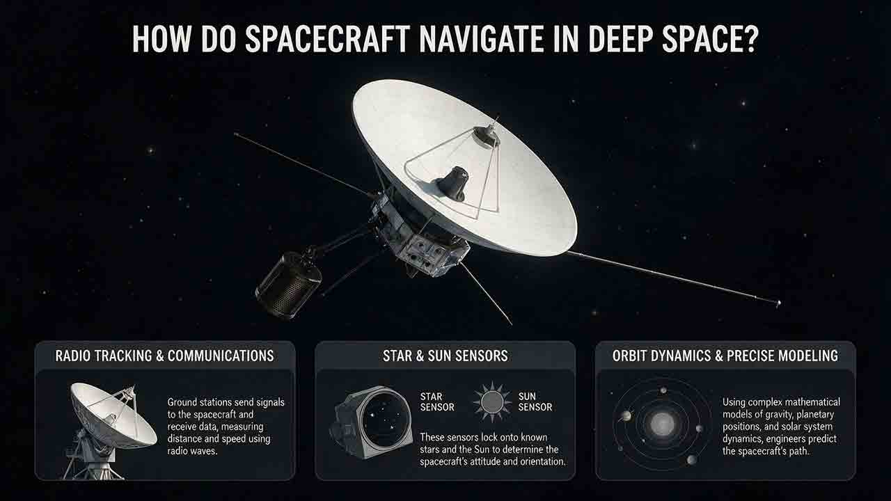
How Do Spacecraft Navigate in Deep Space?
Spacecraft navigate in deep space by comparing a predicted trajectory with repeated radio, optical, and onboard measurements. Ground networks measure distance, line-of-sight velocity, and angular direction. Cameras add destination-relative observations, while attitude sensors establish the spacecraft’s pointing direction. Navigation software combines those observations with force models, estimates position and velocity with uncertainty, and determines whether a trajectory correction is needed.
Explore More Topics
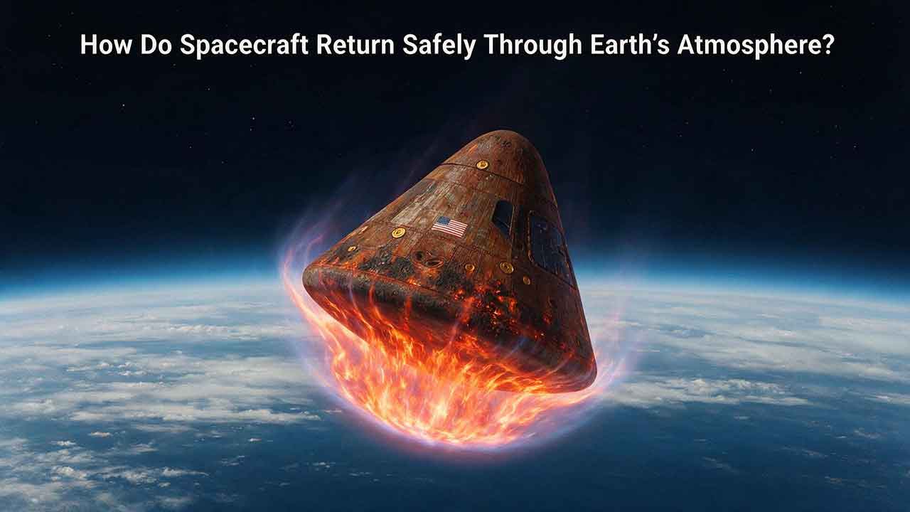
How Do Spacecraft Return Safely Through Earth’s Atmosphere?
Spacecraft return safely through Earth’s atmosphere by managing an enormous amount of energy through a carefully coordinated sequence of trajectory control, thermal protection, aerodynamic deceleration, landing, and recovery. This article explains how deorbit burns and entry corridors guide a spacecraft toward its landing region, why blunt heat shields reduce the danger of hypersonic heating, and how guidance systems control attitude, range, and structural loads. It includes an original comparison of low-Earth-orbit and lunar-return energy, a practical review of ablative and reusable heat-shield technologies, and the CosmoBasics Four-Layer Reentry Framework covering path, protection, control, descent, and recovery. Real-world lessons from Artemis I and the crewed Artemis II mission show why postflight inspection remains essential even after a successful splashdown. Readers will also learn how parachutes, wings, landing rockets, flotation systems, and recovery teams complete the return safely.

How Do Astronauts Sleep, Eat, and Exercise in Space?
Astronauts must redesign ordinary routines when they live in microgravity. This article explains how crew members sleep in secured bags inside ventilated quarters, prepare packaged meals without letting food or liquids drift through the cabin, and use specialized exercise equipment to protect their physical condition. It examines the roles of the Advanced Resistive Exercise Device, the T2 treadmill, and the CEVIS cycle ergometer, while clarifying the difference between active workout time and the full scheduled exercise period. Readers will also learn why tortillas are practical in space, how airflow affects sleep, why ordinary weights do not work normally in orbit, and how nutrition, rest, and exercise support one another. NASA and ESA sources provide the factual foundation, while original comparison tables and practical evaluation frameworks show how spacecraft systems replace functions normally supplied by gravity. The article also distinguishes current International Space Station practices from possible future Moon and Mars mission requirements.

What Happens to the Human Body in Microgravity?
Microgravity changes the human body because fluids are no longer pulled toward the legs, muscles and bones receive less mechanical loading, and the brain loses gravity as a dependable orientation signal. This article explains how weightlessness affects balance, circulation, muscle strength, bone density, vision, blood, immunity, digestion, sleep, and spinal length. It also examines why astronauts may struggle to stand or walk after landing and how exercise, nutrition, monitoring, and rehabilitation help reduce these risks. Two original tools—the Load–Flow–Orientation Framework and the Gravity-Transition Readiness Matrix—connect physiological changes with real mission demands. Drawing on NASA standards, NASA technical reports, ESA materials, and peer-reviewed human spaceflight research, the guide clearly separates established observations from experimental countermeasures and unresolved questions. It also explains what these effects could mean for future missions to the Moon and Mars without treating population averages as predictions for individual astronauts.