How Do Spacecraft Control Their Direction in Space?

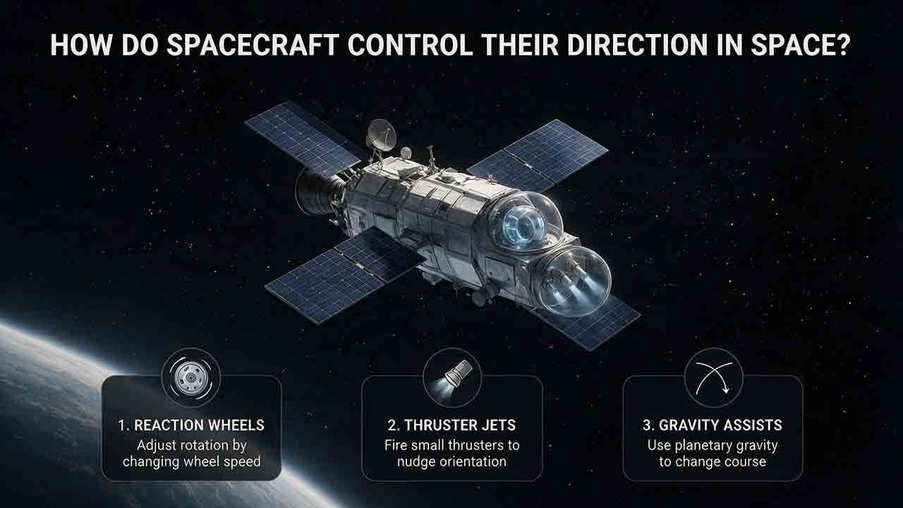
How Do Spacecraft Control Their Direction in Space?
Spacecraft control their direction by measuring their orientation, comparing it with a commanded attitude, and applying torque through reaction wheels, thrusters, control moment gyroscopes, or magnetic torquers. Some spacecraft also use spin stabilization, which relies on angular momentum to resist unwanted changes in orientation. Onboard software checks the result and continuously corrects any remaining pointing error.
Key Takeaways
- A spacecraft’s attitude is its orientation, while its trajectory is the path it follows through space.
- Star trackers, Sun sensors, magnetometers, gyroscopes, and other sensors help determine which way a spacecraft is pointing.
- Reaction wheels provide smooth, precise pointing without consuming propellant during nominal operation, but their momentum capacity is finite.
- Thrusters provide external control torque when the propulsion system is operational, but every firing consumes propellant.
- Direction control is a system-level problem involving sensors, estimation software, actuators, power, momentum management, structural dynamics, and fault protection.
This article explains how spacecraft determine and change their orientation, compares the main attitude-control methods, works through two hypothetical calculations, and provides a practical framework for understanding why different missions use different systems.
What Is the Difference Between Attitude and Trajectory?
Attitude describes which way a spacecraft is facing. Trajectory describes where it is moving.
A spacecraft can rotate around its center of mass without intentionally changing its orbit. An Earth-observation satellite, for example, can turn its camera toward a new target while continuing along approximately the same orbital path.
A commanded orbital change normally requires a change in velocity, most often produced by propulsion. A spacecraft may also deliberately use an external interaction, such as a gravity assist, to alter its planned trajectory. In every case, trajectory changes follow from forces acting over time rather than from attitude rotation alone.
Attitude and trajectory often have to be controlled together. Before an engine burn, the attitude-control system points the engine in the required direction. The propulsion system then changes the spacecraft’s velocity.
NASA’s Small Spacecraft Systems Virtual Institute describes an Attitude Determination and Control System, or ADCS, as the part of a guidance, navigation, and control system that uses sensors, actuators, processors, and software to determine and control spacecraft attitude and spin rate. Common actuators include reaction wheels, magnetic torquers, and thrusters. NASA’s Guidance, Navigation, and Control overview explains these components in greater detail.
How Is Spacecraft Orientation Described?
Most spacecraft attitude motion is described around three body-fixed axes.
The descriptions below use a conventional vehicle analogy to make the rotations easier to visualize. Actual spacecraft axis definitions depend on the body coordinate system selected by the mission, and many spacecraft do not have a clearly defined “nose.”
| Axis | Rotation | Conventional analogy | Example effect |
|---|---|---|---|
| Side-to-side axis | Pitch | The forward end moves up or down | Raises or lowers a camera’s view |
| Top-to-bottom axis | Yaw | The forward end turns left or right | Redirects an antenna or instrument |
| Front-to-back axis | Roll | The body rotates around its length | Changes payload or solar-array orientation |
Engineers must define the positive direction of each axis before interpreting an attitude command or measurement.
Onboard computers may represent orientation with Euler angles, rotation matrices, or quaternions. Quaternions are commonly used in flight software because they describe three-dimensional rotations without the singularity associated with certain Euler-angle sequences.
The essential task is the same regardless of the mathematical representation: the spacecraft needs a reliable estimate of its current orientation and a precise definition of its desired orientation.
How Does a Spacecraft Control Its Direction Step by Step?
Spacecraft direction control is a closed-loop process. A spacecraft does not simply operate an actuator for a preset time and assume that it reached the correct orientation.
Instead, it repeatedly senses its motion, estimates its attitude, calculates an error, applies torque, and checks the result.
Step 1: Define the desired attitude
Mission software first determines where the spacecraft should point.
The target may be:
- the Sun for electrical power;
- Earth for communication;
- a star, galaxy, planet, or moon for scientific observation;
- a surface feature for imaging;
- the required engine direction for a maneuver;
- a thermally safe orientation during an anomaly.
The command may come from a stored mission sequence, autonomous targeting software, an onboard navigation solution, or instructions uploaded from Earth.
Step 2: Measure reference directions and rotation
Attitude sensors collect information about orientation and angular motion.
A star tracker observes star patterns. A Sun sensor determines the Sun’s direction. A magnetometer measures the surrounding magnetic-field vector, while a gyroscope measures rotational rate.
These sensors provide different types of information. Absolute-reference sensors help correct long-term attitude errors, while gyroscopes provide rapid short-term measurements during turns or temporary interruptions in celestial observations.
Step 3: Estimate the current attitude
The flight computer combines sensor readings with a mathematical model of spacecraft motion.
This process is called attitude determination. Estimation and filtering algorithms reduce measurement noise, estimate sensor bias, and maintain an attitude solution when one reference becomes temporarily unavailable.
During Artemis I, Orion used star trackers and inertial measurement units as important inputs to its broader guidance, navigation, and control system. NASA tested the alignment between these sensors under different thermal conditions and also exercised Orion’s reaction-control thrusters.
Star trackers measured star positions to help determine orientation. Orion’s inertial measurement units contained gyroscopes for measuring body rotation rates and accelerometers for measuring acceleration. NASA documented the Artemis I tests on November 27, 2022.
Step 4: Calculate the pointing error
The controller compares the estimated attitude with the commanded attitude.
The difference is the attitude error. The software may also consider:
- current angular rate;
- actuator torque limits;
- reaction-wheel momentum limits;
- flexible solar arrays or antennas;
- structural vibration;
- sensor confidence;
- thermal and bright-object restrictions;
- power and propellant constraints.
A large attitude error may require a planned slew maneuver. A small error may need only a gentle correction to maintain stable pointing.
Step 5: Command the actuators
The controller converts the attitude error into torque commands.
Depending on the spacecraft and operating mode, those commands may go to:
- reaction wheels;
- control moment gyroscopes;
- attitude-control thrusters;
- magnetic torquers;
- a combination of several actuator types.
Step 6: Slow the rotation and prevent overshoot
The spacecraft must stop rotating as it approaches the target attitude.
The controller reduces or reverses the applied torque. Sensors continue measuring rotation rate and pointing error so the spacecraft does not overshoot the commanded orientation.
Step 7: Hold the new attitude
Once the target is reached, the spacecraft continues making small corrections.
Solar radiation pressure, gravity-gradient torque, atmospheric drag in low Earth orbit, magnetic interactions, moving mechanisms, and other disturbances can gradually alter its attitude.
The complete control loop can be summarized as:
Sense → Estimate → Compare → Act → Verify
This framework applies broadly to small satellites, space telescopes, planetary probes, crewed spacecraft, and orbital stations.
Which Sensors Tell a Spacecraft Where It Is Pointing?
Most spacecraft combine several sensor types because no single sensor performs every task under every operating condition.
| Sensor | Main measurement | Best strength | Main limitation |
|---|---|---|---|
| Star tracker | Orientation relative to known stars | Precise absolute attitude reference | Sensitive to bright objects, stray light, and unsuitable fields of view |
| Sun sensor | Direction of the Sun | Simple reference for power-safe pointing | Usually cannot determine complete three-axis attitude alone |
| Gyroscope or inertial measurement unit | Angular rotation rate | Fast updates during maneuvers | Bias and drift accumulate over time |
| Magnetometer | Local magnetic-field direction | Small, low-power reference near a body with a modeled magnetic field | Requires a suitable field and an accurate environmental model |
| Earth or horizon sensor | Direction of Earth or its limb | Useful for Earth-pointing spacecraft | Limited to appropriate near-Earth operations |
| Fine guidance sensor | Position of selected guide objects | Supports highly stable scientific pointing | Specialized and mission-specific |
NASA’s description of the Hubble Space Telescope illustrates how multiple sensors can support different stages of attitude determination. Hubble uses coarse Sun sensors, a magnetic sensing system, gyroscopes, fixed-head star trackers, and fine guidance sensors. NASA’s Hubble Pointing Control page explains the role of each sensor type.
How does a star tracker determine attitude?
A star tracker is a camera and processor that observes stars and compares their apparent pattern with an onboard catalog.
Once the pattern is identified, the spacecraft can calculate its orientation relative to an inertial celestial reference. Star trackers are particularly useful for precise three-axis attitude knowledge.
Their performance depends on obtaining a usable field of view. Spacecraft design and mission planning must account for bright objects, stray light, thermal effects, and temporary obstructions.
Why does a spacecraft also need gyroscopes?
A gyroscope measures angular rate rather than directly identifying an external reference.
Gyroscopes provide rapid updates during a slew and can propagate an attitude estimate when a star tracker or another absolute-reference sensor is temporarily unavailable. However, even small bias errors accumulate over time.
NASA notes that mechanical and non-mechanical inertial sensors experience drift. Flight software can estimate and compensate for part of that drift, but correction from an external reference remains important. NASA’s Chapter 11: Onboard Systems provides a general explanation of inertial and celestial attitude references.
When are Sun sensors and magnetometers useful?
Sun sensors are valuable during initial acquisition, low-power operation, recovery, and safe modes. They can help a solar-powered spacecraft establish a power-positive attitude when fine-pointing sensors are unavailable.
Magnetometers measure the local magnetic-field vector. In Earth orbit, that measurement can be compared with a magnetic-field model to support attitude estimation.
Magnetic-field-based sensing and control become much less useful far from Earth. Deep-space spacecraft cannot rely on Earth’s magnetic field and therefore require other attitude references and control methods. NASA discusses this environmental limitation in its small-spacecraft GNC overview.
How Do Reaction Wheels Turn a Spacecraft?
A reaction wheel is an electrically driven flywheel mounted inside a spacecraft.
When the motor accelerates the wheel in one direction, conservation of angular momentum causes the spacecraft body to rotate in the opposite direction. Slowing the wheel or changing its speed produces a corresponding control torque.
Three suitably oriented and independently commanded wheels can provide nominal three-axis torque authority in a properly designed configuration. Complete attitude control also depends on suitable sensors, estimation software, wheel torque, momentum capacity, axis geometry, and control laws.
Some missions add one or more wheels or use a skewed wheel configuration to provide redundancy and distribute torque and momentum among several axes.
What are the main advantages and limitations?
Reaction wheels provide smooth, reversible torque without consuming propellant during nominal pointing. They are well suited to long observations and repeated small slews.
Their principal limitations are finite speed and momentum capacity, mechanical wear, vibration, and limited torque for rapid maneuvers. A spacecraft using reaction wheels also needs a method for unloading accumulated momentum.
NASA states that reaction-wheel selection must account for spacecraft moment of inertia, required momentum-storage capacity, and mission slew-rate requirements. Once a wheel reaches its maximum permitted speed, it becomes saturated and cannot continue storing momentum in the same direction. NASA provides this selection guidance in its reaction-wheel section.
Why Do Reaction Wheels Become Saturated?
A reaction wheel becomes saturated when it approaches its permitted speed or angular-momentum limit.
Small environmental torques continue acting on a spacecraft even when it appears to be holding still. The controller counters those disturbances by gradually changing wheel momentum.
If the net disturbance acts in one direction for long enough, the wheel cannot continue accelerating indefinitely. The spacecraft must unload stored momentum before the wheel reaches its operational limit.
During momentum unloading, also called desaturation or momentum dumping, thrusters or magnetorquers apply external torque while the reaction wheel returns toward a more useful operating speed.
A reaction wheel redistributes angular momentum inside the spacecraft. A thruster or magnetorquer exchanges angular momentum with the external environment.
How Do Thrusters Control Spacecraft Direction?
Attitude-control thrusters expel propellant to produce force. When a thrust line does not pass through the spacecraft’s center of mass, the force creates torque.
Thrusters are arranged so that selected firings can produce rotation, translation, or a controlled combination of both. The exact placement and firing logic depend on spacecraft geometry and mission requirements.
Thrusters may be used for:
- large attitude changes;
- rapid maneuvers;
- reaction-wheel or CMG momentum unloading;
- backup attitude control;
- safe-mode recovery;
- pointing before an orbital maneuver;
- docking or proximity operations;
- vehicles that do not use reaction wheels.
Thrusters can provide attitude-control torque in Earth orbit or deep space when the propulsion system remains operational. Actual availability depends on remaining propellant, propulsion-system temperature, electrical or pressure conditions, valve and thruster health, and mission restrictions on plume contamination or disturbance.
Every firing consumes propellant and may create unwanted translational motion, vibration, or pointing transients. Minimum impulse and firing-duration limits can also make thrusters less suitable for very fine continuous pointing.
For many scientific spacecraft, reaction wheels perform nominal precision pointing while thrusters are reserved for larger maneuvers, momentum unloading, or contingency control. This is a common architecture rather than a universal requirement.
How Do Magnetorquers Turn a Satellite?
A magnetorquer creates a commanded magnetic dipole using a current-driven coil or torque rod, often built around a magnetic core.
The generated dipole interacts with the surrounding planetary magnetic field and produces torque on the spacecraft. Magnetorquers use electrical power but do not consume propellant.
They are commonly considered for Earth-orbiting small spacecraft because they can support:
- detumbling after deployment;
- coarse attitude control;
- Sun acquisition;
- reaction-wheel momentum unloading;
- backup control.
A magnetorquer cannot produce arbitrary torque in every direction at a given instant. Available torque depends on the orientation and strength of the local magnetic field, which changes as the spacecraft moves through orbit.
Magnetorquers are therefore generally part of a time-varying control strategy rather than a complete high-precision pointing solution. Similar methods may be considered near other magnetized bodies, but only when the local field is sufficiently strong, predictable, and compatible with the mission design.
How Are Control Moment Gyroscopes Different from Reaction Wheels?
A control moment gyroscope, or CMG, contains a spinning rotor mounted in one or more gimbals.
A reaction wheel primarily creates torque by changing rotor speed. A CMG primarily creates torque by changing the direction of the rotor’s angular-momentum vector.
For spacecraft requiring high control torque, CMGs can provide much greater torque amplification than conventional reaction-wheel arrangements. The trade-off is increased mechanical and control complexity.
CMG systems must manage gimbal motion, stored momentum, actuator coordination, mechanical loads, unfavorable gimbal configurations, and control singularities.
A CMG singularity is a gimbal configuration in which the available gimbal motions cannot produce the required torque in a particular direction. Flight software must avoid or manage such configurations with an appropriate steering strategy.
The International Space Station uses four double-gimbaled CMGs as a non-propulsive solution for continuous attitude control. NASA Technical Reports Server document 20100021932 discusses the Space Station CMG design and operational experience.
How Does Spin Stabilization Work?
A spin-stabilized spacecraft rotates much like a spinning top. The angular momentum of the rotating spacecraft resists changes to its spin axis, providing passive resistance to some attitude disturbances.
Spin stabilization may reduce the need for continuous three-axis actuator commands. It can suit probes or missions whose instruments benefit from regularly sweeping across the sky or a planetary target.
The trade-off is reduced pointing flexibility. Continuously directed antennas, cameras, engines, and solar arrays may be more difficult to accommodate when the entire spacecraft is spinning. Thrusters or other control devices may still be required to establish, correct, or reorient the spin axis.
NASA’s Juno mission provides a practical example. Juno’s rotation keeps the spacecraft stable in flight, while its fixed instruments receive regular opportunities to observe their targets during close passes over Jupiter. NASA’s Juno mission page describes the spacecraft’s spin-stabilized design and fixed-instrument arrangement.
NASA’s Chapter 11: Onboard Systems also explains the general principle: the angular momentum of a spinning spacecraft resists changes to the spin axis, while occasional thruster firings can alter the spin rate or orientation when required.
Does a Spacecraft Need Engines to Point in Space?
No. A spacecraft can rotate without firing an engine or pushing against air.
Reaction wheels and CMGs exchange angular momentum with the spacecraft body. Magnetorquers generate external torque through interaction with a suitable magnetic field. A spinning spacecraft can also use its existing angular momentum for passive stability.
Thrusters remain important when a mission needs strong external torque, momentum unloading, rapid recovery, trajectory correction, or a propulsive backup mode.
Which Spacecraft Direction-Control Method Is Best?
No single actuator or stabilization method is best for every mission.
| Method | Best strength | Main limitation | Propellant relationship | Typical use |
|---|---|---|---|---|
| Reaction wheels | Smooth, precise pointing | Momentum saturation, vibration, and mechanical life | None for nominal pointing; unloading may use thrusters | Science, imaging, and communication spacecraft |
| Control moment gyroscopes | High control torque | Gimbal complexity and singularity management | None for nominal control; momentum management may use thrusters | Large spacecraft and orbital stations |
| Thrusters | Strong external torque | Finite propellant and firing disturbances | Consumes propellant with every firing | Large slews, recovery, docking, and momentum unloading |
| Magnetorquers | External torque without propellant | Depends on a suitable magnetic field | No propellant; requires a usable local field | Small satellites in Earth orbit |
| Spin stabilization | Passive resistance to attitude disturbances | Limited pointing flexibility | Not inherently propellant-consuming; corrections may use thrusters | Selected probes and scanning missions |
The table describes typical strengths rather than universal performance levels. Actual capability depends on component design, spacecraft inertia, actuator arrangement, control software, power, structural dynamics, and mission environment.
A Practical Framework for Choosing an Attitude-Control Architecture
This article uses an original educational framework to organize established spacecraft-control principles. It is not a proprietary engineering model, flight-validated algorithm, or substitute for formal spacecraft design analysis.
1. Start with the pointing objective
Ask what must be pointed and how precisely.
- A communication spacecraft must keep an antenna aligned.
- An imaging satellite must stabilize its line of sight.
- A telescope may need extremely low jitter.
- A crewed vehicle may prioritize maneuverability and recovery authority.
- A simple probe may accept spin stabilization.
“Pointing accuracy” alone is not enough. Engineers must distinguish attitude knowledge, control error, stability, jitter, and settling time.
2. Identify the operating environment
The mission environment determines which external references and actuators are available.
- In Earth orbit, magnetometers and magnetorquers may be practical.
- In deep space, Earth’s magnetic field is not a useful control resource.
- In low Earth orbit, atmospheric drag may create disturbance torque.
- Near bright planetary bodies, optical-sensor placement may require additional care.
3. Estimate torque and momentum requirements
Torque determines how quickly the spacecraft can change its rotational rate.
Momentum capacity determines how much accumulated disturbance or maneuver momentum an internal actuator can store.
A reaction wheel may provide sufficient torque for one maneuver but still have insufficient momentum capacity for long-duration operations.
4. Check power and propellant budgets
Reaction wheels, CMGs, sensors, and processors require electrical power. Thrusters require propellant and may also depend on heaters, valves, pressurization equipment, or power-processing hardware.
The architecture must remain viable throughout the mission, including degraded-power conditions and contingency operations.
5. Consider payload sensitivity
An actuator that can point the spacecraft may still be unsuitable for the payload.
Reaction-wheel vibration, thruster impulses, flexible solar-array motion, thermal deformation, and mechanism movement can disturb a sensitive telescope or camera.
6. Plan momentum management
Any reaction-wheel or CMG architecture needs a credible method for managing accumulated angular momentum.
Possible methods include:
- thruster unloading;
- magnetic unloading in a suitable planetary field;
- planned attitude profiles that reduce disturbance accumulation;
- deliberate use of predictable environmental torques.
7. Design for failure
A practical system must define what happens after the loss of a sensor, wheel, processor, or thruster.
Possible provisions include:
- an additional reaction wheel;
- more than one star tracker;
- coarse Sun sensors;
- redundant inertial sensors;
- independent thruster branches;
- simplified safe-mode control laws.
The final choice is a system architecture rather than a single device. A workable attitude-control system must match sensors, estimators, actuators, power, momentum management, thermal limits, structural dynamics, and fault protection.
Simplified Spacecraft Pointing Calculation
All values in the following examples are hypothetical teaching assumptions. They are not specifications for a named spacecraft or flight-qualified component.
The torque required to produce angular acceleration around one axis can be estimated with:
[
\tau = I\alpha
]
where:
- (\tau) is torque in newton-metres;
- (I) is rotational moment of inertia in kilogram-metres squared;
- (\alpha) is angular acceleration in radians per second squared.
Assume a small spacecraft has a yaw-axis moment of inertia of:
[
I = 12\ \text{kg·m}^2
]
Assume the desired angular acceleration is:
[
\alpha = 0.002\ \text{rad/s}^2
]
The ideal rigid-body torque is:
[
\tau
12\ \text{kg·m}^2
\times
0.002\ \text{rad/s}^2
0.024\ \text{N·m}
]
Suppose a candidate reaction wheel can produce:
[
\tau_{\text{wheel}} = 0.030\ \text{N·m}
]
Its nominal torque-to-requirement ratio would be:
[
\frac{0.030}{0.024} = 1.25
]
That ratio alone does not establish suitability. A real design must also account for disturbance torque, control margin, mass-property uncertainty, wheel-axis geometry, structural flexibility, momentum capacity, electrical limits, and failure cases.
How long would an ideal 30-degree slew take?
For a simplified symmetric maneuver, assume the spacecraft accelerates at a constant rate for half the maneuver and then decelerates at the same rate.
The ideal maneuver time is:
[
t_{\text{total}}
2\sqrt{\frac{\theta}{\alpha}}
]
For:
[
\theta = 30^\circ = 0.524\ \text{rad}
]
and:
[
\alpha = 0.002\ \text{rad/s}^2
]
the result is:
[
t_{\text{total}}
2\sqrt{\frac{0.524}{0.002}}
\approx
32.4\ \text{s}
]
This simplified result does not include settling time, actuator rate limits, flexible appendages, sensor noise, wheel saturation, pointing restrictions, or the smoother acceleration profiles used by real spacecraft.
Simplified Reaction-Wheel Momentum Example
Wheel momentum buildup can be approximated with:
[
\Delta H = \tau_d t
]
where:
- (\Delta H) is accumulated angular momentum;
- (\tau_d) is disturbance torque;
- (t) is elapsed time.
Assume a constant disturbance torque of:
[
\tau_d = 10\ \mu\text{N·m}
]
If that hypothetical torque acts in the same direction for six hours:
[
\Delta H
10 \times 10^{-6}\ \text{N·m}
\times
21{,}600\ \text{s}
0.216\ \text{N·m·s}
]
Assume the wheel has a hypothetical usable momentum capacity of:
[
H_{\text{usable}} = 0.5\ \text{N·m·s}
]
The fraction of the assumed capacity used would be:
[
\frac{0.216}{0.5}
0.432
43.2%
]
This percentage assumes that the wheel begins at the selected zero-momentum reference and that the projected disturbance acts continuously along the controlled axis without unloading. It also assumes that the wheel or wheel array absorbs the full projected disturbance and that 0.5 N·m·s represents usable capacity in that direction rather than total nameplate capacity.
The 10 μN·m disturbance torque, 0.5 N·m·s usable capacity, and resulting 43.2% ratio are teaching assumptions only. They cannot be used to infer the unloading frequency, wheel life, operating margin, or disturbance environment of a real mission.
The example demonstrates a broader principle: a small persistent torque can accumulate significant angular momentum over time.
Nancy Grace Roman Space Telescope
NASA’s Roman Space Telescope uses reaction wheels for precise repointing. Changing individual wheel speeds allows the observatory to rotate around its center of mass without using propellant for each nominal pointing adjustment.
NASA states that Roman has six reaction wheels rather than the three needed to produce torque around three independent directions. The six-wheel arrangement provides more angular momentum for faster pointing and complete redundancy if any one wheel fails. NASA released “Moving Roman – Reaction Wheels” on April 23, 2024.
ESA’s Proba-2
ESA’s Proba-2 is a three-axis-stabilized spacecraft. Four reaction wheels supply turning torque, and magnetorquers can unload the wheels.
Its attitude-determination equipment includes a two-head star tracker and a three-axis magnetometer. GPS supports position determination and orbit propagation rather than replacing the spacecraft’s attitude sensors. ESA describes the spacecraft configuration on its Proba-2 page.
NASA’s Orion spacecraft
During Artemis I, NASA tested Orion’s star trackers under different thermal conditions and conducted a reaction-control-thruster flight test.
The example demonstrates the separation between sensing and actuation. Star trackers and inertial measurement units provide inputs to the broader guidance, navigation, and control system, while thrusters physically change the spacecraft’s rotational motion.
The International Space Station
The International Space Station uses four double-gimbaled control moment gyroscopes for non-propulsive attitude control.
The CMGs exchange angular momentum with the station structure. Propulsive systems remain available for operations and conditions that cannot be managed by the CMG system alone. NASA’s Space Station Control Moment Gyroscope report discusses the hardware and operational lessons.
NASA’s Juno spacecraft
Juno uses spin stabilization rather than relying on continuous three-axis reaction-wheel control.
Its rotation keeps the spacecraft stable, and its fixed instruments receive regular opportunities to observe their targets during close passes over Jupiter. NASA’s Juno mission page describes this relationship between spacecraft rotation and instrument viewing.
What Happens When Direction Control Has a Problem?
Fault-protection software may check sensor consistency, angular rates, actuator limits, power state, thermal conditions, and other indicators.
The exact response is mission-specific, but several general patterns are common.
The star tracker cannot determine attitude
Possible causes include bright-object interference, stray light, excessive rotation, thermal effects, or an unsuitable field of view.
The spacecraft may temporarily propagate its attitude with gyroscopes, consult another star tracker, use Sun sensors, reduce its rotation rate, or move toward an orientation that permits celestial-reference reacquisition.
A reaction wheel approaches saturation
Persistent environmental torque, repeated maneuvers, moving appendages, or an actuator problem can increase stored wheel momentum.
The controller may redistribute momentum among available wheels and schedule an unloading maneuver using thrusters or magnetorquers.
Attitude sensors disagree
Sensor disagreement may result from bias, calibration error, thermal change, obstruction, noise, or hardware degradation.
The flight computer may compare redundant measurements, reject data that fails validity checks, adjust sensor weighting, or enter a less precise but more robust control mode.
Fine pointing becomes unstable
Possible causes include structural vibration, reaction-wheel imbalance, flexible appendage motion, noisy measurements, thermal distortion, or an unsuitable controller response.
The spacecraft may reduce its slew rate, change control parameters, suspend precision observations, or isolate the suspected sensor or actuator.
The spacecraft enters safe mode
Safe mode is a protective operating state rather than one universal attitude.
A spacecraft may suspend science operations and prioritize electrical power, thermal safety, attitude stability, and communication. Some spacecraft seek a Sun-pointing or power-positive orientation, while others must also satisfy antenna, instrument, or thermal restrictions.
“A spacecraft needs air to turn”
It does not. Reaction wheels exchange angular momentum internally, thrusters expel propellant, magnetorquers interact with an external magnetic field, and spinning spacecraft use their existing angular momentum for stability.
“Attitude and orbit are the same thing”
Attitude describes orientation. Orbit or trajectory describes motion through space.
A spacecraft may change one without intentionally changing the other, although some thruster operations can affect both.
“A star tracker turns the spacecraft”
A star tracker is a sensor. It estimates orientation by observing stars.
An actuator such as a reaction wheel, CMG, thruster, or magnetorquer creates the torque that changes the attitude.
“Reaction wheels provide unlimited propellant-free control”
Reaction wheels do not consume propellant during nominal operation, but their speed and momentum capacity are finite. They also have mechanical, electrical, thermal, and vibration limits.
Spacecraft Direction-Control Design Checklist
A credible attitude-control concept should answer the following questions:
- What objects must the spacecraft point toward?
- What attitude knowledge and control accuracy are required?
- What pointing stability, jitter, and settling-time limits apply?
- How quickly must the spacecraft turn?
- What are its moments of inertia around each axis?
- Which disturbance torques act in the mission environment?
- Which sensors provide absolute attitude references?
- How will inertial-sensor drift be corrected?
- What actuator torque is required?
- How much momentum must internal actuators store?
- How will reaction wheels or CMGs be unloaded?
- Is a useful planetary magnetic field available?
- How much electrical power can the system use?
- How much propellant can be allocated to attitude control?
- Could actuator vibration disturb the payload?
- How do flexible structures affect the controller?
- What happens after the loss of one sensor or actuator?
- Which attitude protects power generation and thermal safety?
- Can the spacecraft recover without immediate commands from Earth?
What Should Readers Take Away?
Spacecraft control their direction through a coordinated system of attitude sensors, estimation software, feedback controllers, and torque-producing actuators.
The clearest mental model is:
Sense → Estimate → Compare → Act → Verify
The correct hardware cannot be selected in isolation. Sensors, actuators, power, momentum unloading, structural behavior, thermal limits, mission environment, and fault protection must function as one integrated attitude-control architecture.
How does a spacecraft stop rotating after a turn?
The controller commands torque in the opposite direction as the spacecraft approaches its target attitude. Sensors measure the decreasing angular rate, and the feedback loop adjusts the torque until rotation is stopped within the permitted tolerance.
Can one reaction wheel control every direction?
One reaction wheel produces torque mainly along its spin axis.
When reaction wheels are the primary actuators, several suitably oriented and independently commanded wheels are needed to provide nominal torque authority around three axes. Additional wheels may provide redundancy and distribute torque and momentum.
What is the difference between pointing knowledge and pointing control?
Pointing knowledge describes how accurately the spacecraft knows its attitude. Pointing control describes how closely it can reach or maintain the commanded attitude.
A spacecraft can have an accurate attitude estimate but insufficient actuator authority, or strong actuators but inadequate attitude knowledge.
Can a spacecraft control its direction without commands from Earth?
Yes. Onboard software can process sensor data, estimate attitude, calculate pointing errors, command actuators, enter safe mode, and perform scheduled maneuvers autonomously.
Ground teams still plan operations, upload commands, review telemetry, and update software or operating parameters.
What usually limits extremely precise pointing?
Possible limitations include sensor noise, gyro bias, reaction-wheel vibration, structural flexibility, thermal deformation, actuator resolution, calibration error, and environmental disturbance torque.
The dominant limitation depends on the spacecraft, payload, orbit, and observation mode.
What happens if a star tracker is temporarily blinded?
The spacecraft may rely on gyroscopes, Sun sensors, magnetometers, another star tracker, or a propagated attitude estimate until a valid celestial reference is restored.
The available fallback depends on the spacecraft’s sensor redundancy and operating environment.
Editorial Approach
This article was prepared from NASA and ESA technical, educational, and mission materials together with established spacecraft-engineering principles. Particular attention was given to the distinction between attitude and trajectory, the documented functions of Orion’s sensors, Juno’s spin-stabilized design, and the arithmetic consistency of the simplified calculations.
The numerical examples are educational assumptions rather than flight-hardware specifications or mission-design recommendations. The article explains published engineering concepts and does not report original spacecraft hardware testing.
Sources
National Aeronautics and Space Administration. “5.0 Guidance, Navigation, and Control.” State-of-the-Art of Small Spacecraft Technology. Accessed July 31, 2026.
National Aeronautics and Space Administration. “Chapter 11: Onboard Systems.” Basics of Space Flight. Accessed July 31, 2026.
National Aeronautics and Space Administration. “Pointing Control.” Hubble Space Telescope. Accessed July 31, 2026.
Jones, Sandra. “Artemis I – Flight Day 12: Orion Star Trackers, Reaction Control Thrusters Tested.” NASA, November 27, 2022. Accessed July 31, 2026.
NASA Goddard Space Flight Center. “Moving Roman – Reaction Wheels.” NASA Scientific Visualization Studio, April 23, 2024. Accessed July 31, 2026.
European Space Agency. “Proba-2: Spacecraft.” Accessed July 31, 2026.
Gurrisi, Charles; Seidel, Raymond; Dickerson, Scott; Didziulis, Stephen; Frantz, Peter; and Ferguson, Kevin. “Space Station Control Moment Gyroscope Lessons Learned.” NASA Technical Reports Server, document ID 20100021932, 2010. Accessed July 31, 2026.
National Aeronautics and Space Administration. “Juno.” NASA Science. Accessed July 31, 2026.
More from Spacecraft Engineering
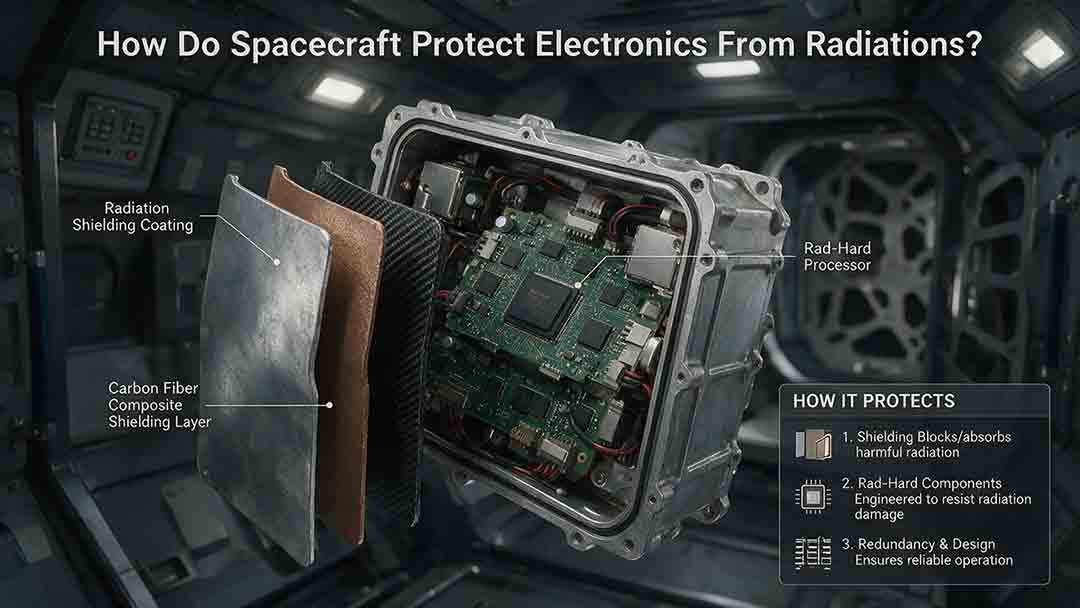
How Do Spacecraft Protect Electronics From Radiation?
Spacecraft protect electronics from radiation through a layered engineering strategy rather than a single protective material. This article explains how total ionizing dose, displacement damage, single-event effects, and spacecraft charging can disrupt computers, memory, sensors, and power systems. It examines the roles of radiation-hardened components, physical shielding, error-correcting memory, current limiting, watchdog timers, redundancy, fault isolation, and safe-mode recovery. Readers will also learn how engineers model mission-specific radiation environments, evaluate the quality of component test evidence, estimate dose margin, and choose different protection strategies for Earth orbit, deep space, and high-radiation destinations such as Jupiter. Practical comparison tables, a decision framework, real mission examples, a troubleshooting guide, and a design-review checklist show why reliable spacecraft must be able to prevent, detect, contain, and recover from radiation-related faults.
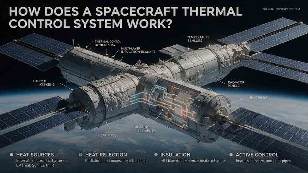
How Does a Spacecraft Thermal Control System Work?
A spacecraft thermal control system keeps onboard equipment within safe operating and survival temperatures by controlling how heat is absorbed, generated, transported, stored, and released. This guide explains how passive technologies—including multilayer insulation, thermal coatings, heat pipes, straps, and radiators—work alongside active systems such as heaters, temperature sensors, cryocoolers, and pumped fluid loops. It introduces the original Protect–Move–Reject–Trim–Verify framework for understanding complete spacecraft heat paths and provides practical tools for evaluating thermal designs. Readers will also find a worked radiator-sizing example, a thermal-resistance calculation, mission-specific selection guidance, common design mistakes, troubleshooting methods, and real examples from the James Webb Space Telescope, International Space Station, and Europa Clipper. Based on publicly available NASA and ESA documentation, the article distinguishes simplified educational calculations from actual flight-design analysis while showing why spacecraft must be protected from both overheating and excessive cooling.
How Do Spacecraft Communicate With Earth?
Spacecraft communicate with Earth by sending encoded information through radio waves or laser light. This guide explains the complete path from an onboard instrument and computer to a transmitter, antenna, ground station, and mission-control center. It covers uplinks, downlinks, telemetry, tracking, direct-to-Earth communication, relay satellites, spacecraft crosslinks, and onboard data storage. Readers will also learn why signals weaken over distance, how communication delays are calculated, and how antenna gain, transmitter power, data rate, coding, pointing accuracy, and ground-network availability affect link reliability. Worked examples show how long a signal may take to travel between Mars and Earth and how much data can be returned during a scheduled contact. Real mission examples—including NASA’s Deep Space Network, the Mars Relay Network, the James Webb Space Telescope, and the DSOC optical demonstration—show how these engineering principles are applied in practice.
Explore More Topics
How Do Spacecraft Return Safely Through Earth’s Atmosphere?
Spacecraft return safely through Earth’s atmosphere by managing an enormous amount of energy through a carefully coordinated sequence of trajectory control, thermal protection, aerodynamic deceleration, landing, and recovery. This article explains how deorbit burns and entry corridors guide a spacecraft toward its landing region, why blunt heat shields reduce the danger of hypersonic heating, and how guidance systems control attitude, range, and structural loads. It includes an original comparison of low-Earth-orbit and lunar-return energy, a practical review of ablative and reusable heat-shield technologies, and the CosmoBasics Four-Layer Reentry Framework covering path, protection, control, descent, and recovery. Real-world lessons from Artemis I and the crewed Artemis II mission show why postflight inspection remains essential even after a successful splashdown. Readers will also learn how parachutes, wings, landing rockets, flotation systems, and recovery teams complete the return safely.
How Do Astronauts Sleep, Eat, and Exercise in Space?
Astronauts must redesign ordinary routines when they live in microgravity. This article explains how crew members sleep in secured bags inside ventilated quarters, prepare packaged meals without letting food or liquids drift through the cabin, and use specialized exercise equipment to protect their physical condition. It examines the roles of the Advanced Resistive Exercise Device, the T2 treadmill, and the CEVIS cycle ergometer, while clarifying the difference between active workout time and the full scheduled exercise period. Readers will also learn why tortillas are practical in space, how airflow affects sleep, why ordinary weights do not work normally in orbit, and how nutrition, rest, and exercise support one another. NASA and ESA sources provide the factual foundation, while original comparison tables and practical evaluation frameworks show how spacecraft systems replace functions normally supplied by gravity. The article also distinguishes current International Space Station practices from possible future Moon and Mars mission requirements.
What Happens to the Human Body in Microgravity?
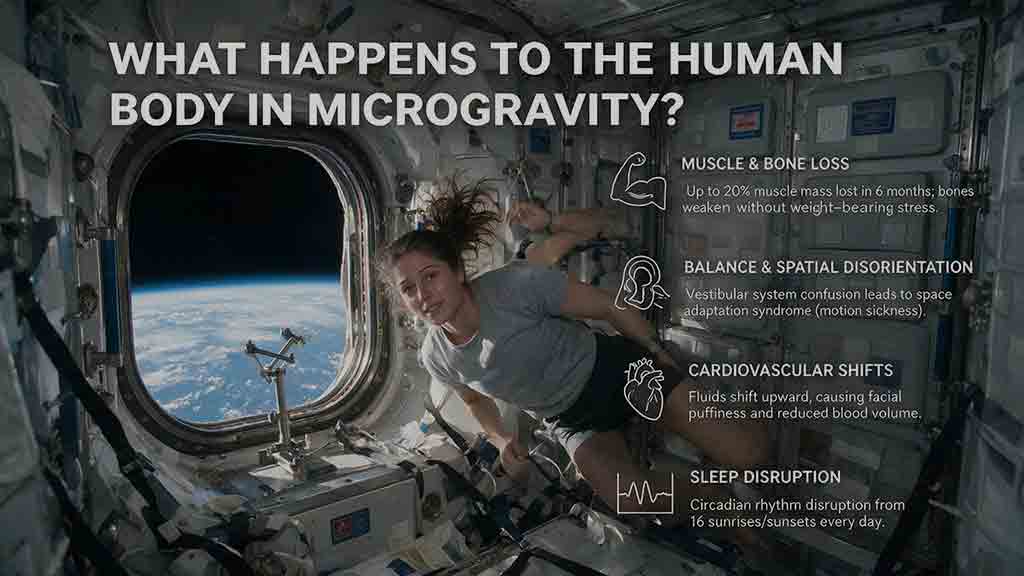
Microgravity changes the human body because fluids are no longer pulled toward the legs, muscles and bones receive less mechanical loading, and the brain loses gravity as a dependable orientation signal. This article explains how weightlessness affects balance, circulation, muscle strength, bone density, vision, blood, immunity, digestion, sleep, and spinal length. It also examines why astronauts may struggle to stand or walk after landing and how exercise, nutrition, monitoring, and rehabilitation help reduce these risks. Two original tools—the Load–Flow–Orientation Framework and the Gravity-Transition Readiness Matrix—connect physiological changes with real mission demands. Drawing on NASA standards, NASA technical reports, ESA materials, and peer-reviewed human spaceflight research, the guide clearly separates established observations from experimental countermeasures and unresolved questions. It also explains what these effects could mean for future missions to the Moon and Mars without treating population averages as predictions for individual astronauts.