How Do Spacecraft Protect Electronics From Radiation?

How Do Spacecraft Protect Electronics From Radiation?
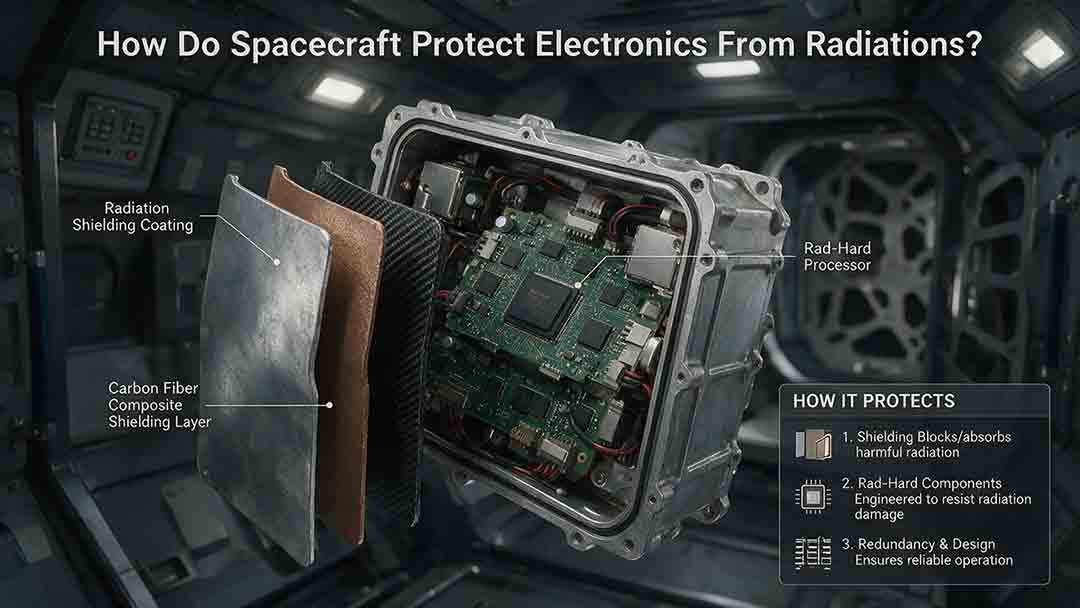
Spacecraft protect electronics from radiation by combining shielding, radiation-hardened or radiation-tolerant components, fault-resistant circuits, error-correcting software, redundancy, and recovery procedures. Engineers model the mission’s radiation environment, estimate how each component may fail, and build several layers of protection so that radiation damage can be prevented, detected, contained, or recovered from.
Key Takeaways
- No single shield, component, or software feature makes spacecraft electronics immune to radiation.
- Engineers evaluate total ionizing dose, displacement damage, single-event effects, and spacecraft charging as different problems.
- Radiation-hardened hardware is most effective when supported by error correction, current limiting, watchdogs, redundancy, and safe modes.
- Additional shielding can help, but excessive or poorly selected shielding adds mass and may generate secondary radiation.
- Every protection strategy must be matched to the mission’s orbit, duration, spacecraft geometry, critical functions, and acceptable risk.
This guide explains how radiation affects electronics, how engineers build a complete protection strategy, how different hardware choices compare, and how spacecraft recover when radiation-related faults still occur.
The article was researched using current ECSS requirements, NASA and JPL radiation-effects resources, ESA engineering tools, NOAA environment information, and first-party mission documentation. It does not rely on independent laboratory testing. The numerical example is hypothetical and is intended to explain the reasoning process rather than qualify a real component.
How Does Space Radiation Damage Electronics?
Space radiation can gradually change a component’s electrical characteristics, damage its semiconductor structure, or trigger an immediate fault when one energetic particle crosses a sensitive region.
The current ECSS-Q-ST-60-15C Rev.1 radiation-hardness assurance standard addresses three principal effects on electronic components: total ionizing dose, total non-ionizing dose or displacement damage, and single-event effects. Spacecraft charging is an important related problem, but the standard treats it as outside that document’s scope.
| Radiation problem | One-sentence definition | Possible consequences | Common protections |
|---|---|---|---|
| Total ionizing dose, or TID | Ionizing energy accumulates in semiconductor and insulating materials over time | Leakage current, threshold shifts, timing changes, higher power use, or eventual failure | Tolerant parts, shielding, dose margin, lot testing |
| Displacement damage, or TNID | Energetic particles displace atoms from their normal positions in a material | Greater sensor noise, reduced sensitivity, lower optical output, or solar-cell degradation | Resistant technology, calibration, shielding, degradation allowance |
| Single-event effect, or SEE | One energetic particle deposits enough charge to disturb or damage a device | Bit flip, transient pulse, processor interruption, latchup, burnout, or gate rupture | Hardened circuits, ECC, voting, current limiting, resets, redundancy |
| Spacecraft charging | Electrical charge accumulates on surfaces or inside insulating materials | Electrostatic discharge, interference, false signals, or permanent damage | Grounding, conductive paths, coatings, material control, shielding |
How Does Total Ionizing Dose Affect a Component?
Total ionizing dose is the cumulative ionizing energy absorbed by a material. For electronic parts, it is often expressed in rad(Si) or kilorad(Si), indicating absorbed dose in silicon.
TID often appears as gradual electrical drift rather than one dramatic failure. Trapped charge and interface changes can alter transistor thresholds, leakage current, gain, switching speed, and power consumption.
A component that works correctly early in a mission may move outside its permitted electrical limits after months or years of exposure. Engineers therefore compare the predicted end-of-life dose with applicable test evidence for the actual component technology and, when necessary, the manufacturing lot.
What Is Displacement Damage?
Displacement damage occurs when energetic particles transfer enough momentum to move atoms out of their normal positions in a material’s crystal structure.
The effect can be particularly important for image sensors, photodiodes, optocouplers, solar cells, and other devices whose performance depends on charge moving predictably through semiconductor material.
Possible symptoms include:
- Increased image-sensor dark current
- Greater detector noise
- Reduced optical sensitivity
- Lower optocoupler output
- Declining solar-cell efficiency
- Changes in transistor gain
Restarting a computer cannot reverse most displacement damage. A mission may instead use more tolerant devices, include performance margin, recalibrate an instrument, change its operating conditions, or accept a controlled reduction in performance.
What Are Single-Event Effects?
A single-event effect is a change caused by one energetic particle passing through a sensitive part of an electronic device.
The deposited charge may change stored data, create a temporary pulse, interrupt a processor, activate an unintended current path, or permanently damage a power device.
Common single-event effects include:
- Single-event upset, or SEU: A stored bit changes state.
- Single-event transient, or SET: A temporary pulse appears in an analog or digital circuit.
- Single-event functional interrupt, or SEFI: A device stops operating correctly until it is reset or reconfigured.
- Single-event latchup, or SEL: A parasitic current path activates and may draw damaging current.
- Single-event burnout, or SEB: A power device suffers destructive failure.
- Single-event gate rupture, or SEGR: Radiation damages an insulating gate structure.
A part’s susceptibility depends on its semiconductor process, circuit design, voltage, temperature, operating state, particle type, and deposited energy. NASA and JPL radiation programs therefore assess individual technologies and applications instead of treating “radiation tolerance” as one universal rating. The JPL Radiation Effects Database publishes test information for electronic parts and systems, while the NASA Goddard Radiation Effects and Analysis Group performs component and system-level radiation work.
Which Radiation Environment Must a Spacecraft Survive?
The relevant environment depends on the spacecraft’s orbit or trajectory, mission duration, shielding geometry, solar conditions, orientation, and component locations.
Important natural sources include trapped particles around planets, solar energetic particles, and galactic cosmic rays. NOAA describes Earth’s radiation belts as dynamic populations of energetic electrons and protons that can change over timescales ranging from minutes to years.
| Mission environment | Major concerns | Typical design emphasis |
|---|---|---|
| Low Earth orbit | Trapped protons, South Atlantic Anomaly passages, solar particles, cosmic rays | Upset recovery, orbit-specific dose analysis, instrument operating rules |
| Polar or high-inclination orbit | Increased exposure to solar and cosmic particles | SEE rates, fault recovery, solar-event procedures |
| Medium Earth orbit | Operation within or near strong radiation-belt regions | TID, displacement damage, charging, shielding |
| Geostationary orbit | Energetic electrons, solar particles, internal charging, long exposure | Long-duration dose tolerance, charging control, redundant avionics |
| Lunar or deep-space mission | Solar energetic particles and galactic cosmic rays with less geomagnetic protection | Autonomous recovery, SEE tolerance, long-term degradation |
| Jupiter-system mission | Intense planetary radiation belts, especially energetic electrons | Vaults, local shielding, strict dose allocation, tolerant components |
Low Earth orbit is not uniformly mild. In the South Atlantic Anomaly, Earth’s magnetic field allows trapped particles to approach closer to the planet, increasing exposure for spacecraft passing through the region.
Component placement also matters. Two identical circuit boards may receive different doses if one is behind tanks, batteries, structural panels, or other equipment while the other has a less obstructed path to space.
How Do Engineers Build a Complete Radiation Protection Strategy?
A dependable spacecraft does not rely on a single “radiation-proof” enclosure. It uses a layered protection stack in which each layer addresses a different part of the problem.
The Five-Layer Radiation Protection Stack
| Layer | Engineering question | Typical measures |
|---|---|---|
| 1. Environment definition | What particles, energies, and doses can reach the spacecraft? | Orbit models, mission duration, solar-event assumptions, geometry |
| 2. Component tolerance | Can each device survive the expected environment? | Radiation-hardened parts, tolerant parts, component testing |
| 3. Physical attenuation | Can placement or shielding reduce exposure? | Structural shielding, equipment layout, local shields, vaults |
| 4. Fault containment | Can one fault be stopped from damaging other systems? | Current limiting, isolation, resettable power domains, redundancy |
| 5. Detection and recovery | Can the spacecraft find and correct the remaining faults? | ECC, memory scrubbing, watchdogs, reconfiguration, safe mode |
This framework is useful because every layer has limitations. Shielding cannot stop all high-energy particles, radiation-hardened processors still depend on power and interfaces, and software recovery cannot repair a permanently damaged transistor.
The practical objective is not to promise that faults will never occur. It is to reduce their frequency and prevent a correctable fault from becoming a mission-ending failure.
Step 1: Define the Mission Environment
Engineers begin with the planned trajectory, orbit altitude, inclination, mission duration, launch assumptions, solar conditions, and spacecraft orientation.
They then estimate particle spectra, dose, displacement damage, upset rates, and charging conditions at relevant locations inside the spacecraft.
ESA’s MULASSIS tool models how particle spectra change behind user-defined shielding layers. The Sector Shielding Analysis Tool traces paths through three-dimensional spacecraft geometry to estimate how much surrounding material protects a selected point.
The output is not one universal radiation number. It is a set of estimates for different particles, energies, locations, operating conditions, and mission phases.
Step 2: Classify Functions by Failure Consequence
A corrupted copy of noncritical science data is not equivalent to a failure in the command computer, power controller, propulsion interface, or attitude-control system.
For each function, engineers ask:
- Could its failure end the mission?
- Could it create an unsafe spacecraft state?
- Can incorrect output be detected?
- Can the function be restarted or reconfigured?
- Is an independent backup available?
- Could failure damage connected hardware?
- Must recovery occur without immediate communication with Earth?
Criticality determines where the strongest hardware assurance, independence, and recovery capability are required.
For example, radiation protection for a resettable image processor may differ from protection for the computer that maintains power, communications, and safe pointing. Attitude control and fault recovery must therefore be designed together so the spacecraft can maintain or regain a safe orientation after an upset.
Step 3: Set Separate Requirements for Different Effects
A requirement should not merely state that a device must be “radiation tolerant.” It should identify the effects that matter for the mission and component.
Possible requirements include:
- Minimum verified TID tolerance
- Maximum permitted end-of-life drift
- Displacement-damage tolerance
- Acceptable correctable-upset rate
- Acceptable uncorrectable-error rate
- Latchup immunity or protective shutdown time
- Recovery time after a functional interrupt
- Charging and discharge limits
- Required design or analysis margin
- Required test conditions and sample applicability
ECSS-Q-ST-60-15C Rev.1 describes a project-specific radiation-hardness assurance process and separates TID, TNID, and SEE assessment. Charging must be handled through the appropriate additional engineering process rather than being silently treated as part of one generic radiation rating.
Step 4: Select Components Using Applicable Evidence
Engineers may use radiation-hardened parts, radiation-tolerant parts, characterized commercial parts, or a controlled mixture.
The decision should be supported by relevant evidence. Labels such as “space grade,” “industrial grade,” or “radiation tolerant” do not by themselves establish suitability for a particular mission.
Useful evidence must be examined for:
- Exact part number and revision
- Semiconductor process
- Package
- Manufacturing lot
- Supply voltage
- Temperature
- Device operating state
- Radiation source and particle energy
- Dose rate
- Failure criteria
- Sample size
- Test date and method
NASA’s guidance for selecting commercial electronics in radiation environments emphasizes component-specific susceptibility, mitigation, and selection strategies rather than assuming that all commercial parts present the same risk. The NASA Electronic Parts and Packaging Program also develops technical knowledge about part performance, testing, reliability, and failure modes for spaceflight applications.
An Evidence Quality Ladder
| Evidence level | Example | What it can reasonably support |
|---|---|---|
| Strong | Test data for the flight lot under applicable voltage, temperature, bias, particle, and failure conditions | Detailed mission assessment when the test method and sample size are adequate |
| Moderate | Data for the same part from another lot or under partly different conditions | Risk screening and preliminary selection; additional analysis or testing may be required |
| Limited | Data for a related part or the same semiconductor family | Early comparison only; does not establish flight suitability |
| Weak | Manufacturer marketing, an undefined “space grade” label, or anecdotal use | Cannot independently demonstrate radiation tolerance |
This ladder helps separate useful engineering evidence from descriptions that sound reassuring but lack the conditions needed for a mission decision.
Step 5: Optimize Placement and Shielding
The spacecraft’s structure already provides some shielding. Engineers can reduce exposure further by placing sensitive components behind tanks, batteries, structural panels, or less sensitive equipment.
Local shields may protect a vulnerable part more efficiently than increasing material around the entire spacecraft.
Placement decisions also affect heat rejection, cable routing, access, vibration, and structural loads. For that reason, radiation layout cannot be separated completely from spacecraft thermal control.
Step 6: Prevent Faults From Spreading
Circuit-level protection can stop a temporary event from damaging an entire subsystem.
Common measures include:
- Fast overcurrent detection
- Electronic fuses
- Resettable power switches
- Independent power domains
- Protected clocks
- Input filtering
- Hardware watchdogs
- Interface isolation
- Redundant power regulators
- Controlled power cycling
If a latchup-sensitive component begins drawing excessive current, a protection circuit may disconnect it before overheating causes permanent damage. The spacecraft can later wait, restore power, verify the device, and decide whether it is safe to return it to service.
Because current limiting and power-domain recovery depend on the electrical architecture, they must be coordinated with power generation, storage, distribution, isolation, and fault-recovery design.
Step 7: Protect Data and Software State
Software cannot stop a particle, but it can detect, correct, isolate, and recover from many resulting errors.
Common techniques include:
- Error-correcting code memory
- Memory scrubbing
- Checksums
- Cyclic redundancy checks
- Duplicate calculations
- Range and reasonableness checks
- Protected boot images
- Multiple software copies
- Checkpoint and restart
- Watchdog-triggered reset
- Reconfigurable FPGA logic
- Command and sequence validation
Stored software and configuration data may receive stronger protection than temporary payload data because corruption in boot code can prevent recovery.
Step 8: Test the Components and the Recovery Path
Radiation testing may use heavy ions, protons, electrons, gamma rays, neutrons, or other sources selected for the effect being investigated.
Test teams may monitor:
- Bit errors
- Functional interruptions
- Latchup current
- Transient outputs
- Timing changes
- Leakage current
- Analog drift
- Sensor noise
- Recovery after reset
- Performance after accumulated dose
Testing should not stop at proving that a part survives exposure. Engineers must also verify that current limiters, watchdogs, redundant computers, memory correction, power cycling, safe modes, and telemetry respond correctly.
Fault telemetry is especially important because ground teams must distinguish radiation-related behavior from thermal, software, communication, and power problems. The communications architecture must therefore preserve enough health data, event timing, and diagnostic context for the ground team to identify the likely cause.
Which Is Better: Radiation-Hardened or Commercial Electronics?
Neither approach is automatically best for every function. The appropriate choice depends on mission criticality, processing needs, radiation exposure, duration, power, budget, schedule, and the surrounding system architecture.
| Component approach | Main advantage | Main limitation | Typical use |
|---|---|---|---|
| Radiation-hardened component | High tolerance and established assurance evidence | Higher cost, fewer choices, and sometimes lower processing performance | Command, control, power, communications, and other critical functions |
| Radiation-tolerant component | Balance of tolerance, availability, and capability | Qualification remains device- and mission-specific | Payload electronics, interfaces, communications, control systems |
| Characterized commercial component | High performance and broad availability | Greater testing, containment, and recovery burden | Partitioned or resettable processing workloads |
| Mixed architecture | Places the strongest protection where failure matters most | More interfaces, supervision, and verification work | Missions needing dependable control and advanced computation |
What Is Radiation Hardening by Process?
Radiation hardening by process changes semiconductor materials or manufacturing technology to reduce charge collection, trapped charge, leakage, or parasitic current paths.
Possible approaches include specialized insulating structures and fabrication processes selected for radiation tolerance.
What Is Radiation Hardening by Design?
Radiation hardening by design uses circuit and system techniques to make stored information and logic less vulnerable to radiation-induced charge.
Examples include:
- Hardened storage cells
- Redundant internal nodes
- Voting logic
- Guard structures
- Temporal filtering
- Fault detection and recovery
- Protected power and clock networks
NASA’s High Performance Spaceflight Computer combines a radiation-hard-by-design approach with fault-tolerance and recovery mechanisms.
Can Commercial Components Be Used?
Commercial components can be suitable when their risk is understood and controlled. NASA has used commercial parts in selected spacecraft applications through careful selection, qualification, screening, and system-level mitigation.
A defensible commercial-component strategy may include:
- Applicable radiation testing
- Manufacturing-lot control
- Restricted operating conditions
- Local shielding
- Fault containment
- A trusted supervisory computer
- Resettable power
- Data validation
- Redundant devices
- Acceptance of a documented failure rate
A fast commercial processor is not made dependable merely by placing it inside an aluminum enclosure. Its failure modes must be compatible with the spacecraft’s ability to detect, isolate, reset, or abandon the workload.
How Does Shielding Protect Spacecraft Electronics?
Shielding reduces the number or energy of particles reaching a component. Its value depends on the particle spectrum, material, thickness, geometry, and sensitive device.
Which Shielding Materials Are Used?
Aluminum is a common structural and analytical reference because spacecraft already contain aluminum panels, frames, and enclosures.
Other possible shielding materials include:
- Tantalum
- Lead-containing layers
- Hydrogen-rich materials
- Composite structures
- Graded atomic-number layers
- Specialized local shielding
Dense materials are not automatically superior. Energetic electrons interacting with high-density material can produce bremsstrahlung X-rays, while energetic ions can generate secondary particles.
Engineers therefore use radiation-transport calculations rather than selecting shielding solely by density.
Why Not Add a Thick Metal Shell?
Additional shielding creates costs and secondary effects:
- Increased launch mass
- Higher structural loads
- Reduced internal volume
- Greater thermal-control difficulty
- Possible secondary radiation
- More complex assembly and access
- Higher development cost
A local shield around one sensitive part may be more effective than adding the same mass across the spacecraft.
What Is a Radiation Vault?
A radiation vault is a protected enclosure that places selected electronics behind additional material.
ESA reports that the most sensitive electronics on the Jupiter Icy Moons Explorer, or Juice, are housed inside two vaults whose carbon-fibre walls are reinforced with lead. ESA also describes local shielding made from aluminum and heavier materials such as tantalum.
The vault does not eliminate all radiation. Mission designers used environment models, trajectory choices, component testing, vault shielding, and local spot shielding together to keep exposure within the selected electronics’ capabilities.
How Do Redundancy, ECC, and Safe Mode Handle Remaining Faults?
Some radiation-induced faults will occur even in a carefully protected spacecraft. Fault-tolerant architecture is designed to keep those faults from ending the mission.
How Does Error-Correcting Memory Work?
Error-correcting code memory stores additional check information with each data word. When the word is read, the system uses those check bits to detect and, for supported error patterns, correct corrupted data.
A common implementation can correct a single-bit error and detect certain larger errors. Stronger codes can handle more corruption but require additional storage, logic, power, or processing time.
Why Is Memory Scrubbing Needed?
Correcting an error during a read does not always repair the stored physical value. Memory scrubbing periodically reads protected memory, corrects errors, and writes the corrected data back.
Without scrubbing, separate radiation events can accumulate within one protected word until the error pattern exceeds the code’s correction capability.
ECC cannot correct every failure. It does not repair a failed voltage regulator, destructive latchup, analog drift, sensor degradation, or corruption in an unprotected data path.
How Does Redundancy Help?
A spacecraft may carry two or more computers so that another unit can assume control after a failure.
Redundancy is useful only when the units do not share unacceptable common failure points. Two computers may still fail together if they depend on the same:
- Power regulator
- Clock
- Reset circuit
- Memory source
- Communication interface
- Software defect
- Environmental vulnerability
What Is Triple Modular Redundancy?
Triple modular redundancy performs a calculation in three channels and uses a voter to select the majority result.
TMR is used in some programmable-logic and control applications because it can mask one incorrect channel. Its tradeoffs include additional power, hardware, voting logic, verification work, and possible common-mode failures.
What Is Fault Detection, Isolation, and Recovery?
Fault detection, isolation, and recovery, often abbreviated FDIR, is the process of recognizing an abnormal condition, identifying the affected function, preventing it from spreading, and restoring an acceptable operating state.
A simplified sequence is:
- Detect invalid output, missing response, or excessive current.
- Isolate the affected processor, interface, or power domain.
- Switch to a backup or conservative operating configuration.
- Reset, repower, or reconfigure the affected device.
- Verify that stable operation has returned.
- record diagnostic telemetry.
- Resume activities gradually.
How Does Safe Mode Help?
A safe-mode design may place the spacecraft in a power-positive, thermally acceptable, and communicative state while the cause of a fault is investigated.
Safe mode often limits payload operations and uses conservative pointing and power rules. It should avoid unnecessary dependence on the same complex function that triggered the fault.
How Is Radiation Margin Calculated?
A simplified TID comparison evaluates whether verified component tolerance exceeds the predicted end-of-life dose after applying the project’s chosen uncertainty or design factor.
Hypothetical TID Example
Hypothetical educational values are used below. They are not taken from a specific spacecraft or component qualification report.
Assume:
- Modeled end-of-life dose: 12 krad(Si)
- Example project design factor: 2
- Verified component tolerance: 50 krad(Si)
The example design requirement is:
Design requirement = Modeled dose × Design factor
Design requirement = 12 krad(Si) × 2 = 24 krad(Si)
A simplified tolerance ratio is:
Tolerance ratio = Verified tolerance ÷ Design requirement
Tolerance ratio = 50 ÷ 24 ≈ 2.1
| Input or result | Value | Status |
|---|---|---|
| Modeled end-of-life dose | 12 krad(Si) | Hypothetical input |
| Design factor | 2 | Example assumption |
| Design requirement | 24 krad(Si) | Calculated |
| Verified component tolerance | 50 krad(Si) | Hypothetical input |
| Simplified tolerance ratio | 2.1 | Calculated |
Under this simplified comparison, the component’s verified tolerance is about 2.1 times the assumed design requirement.
That result does not qualify the component. A real assessment must consider:
- Test method
- Bias conditions
- Dose rate
- Temperature
- Annealing
- Sample size
- Lot applicability
- Failure criteria
- Model uncertainty
- Applicable project standards
Standards and mission programs may define margin differently. A satisfactory TID comparison also says nothing by itself about latchup, functional interrupts, displacement damage, charging, or destructive single-event effects.
Juice: Environment Modeling, Vaults, and Local Shielding
Juice must operate in Jupiter’s severe radiation environment. ESA describes a strategy that combines trajectory planning, environmental modeling, component testing, two lead-reinforced electronics vaults, and local shields made from aluminum or heavier materials.
This is a clear example of layered protection. Mission design reduces exposure before hardware solutions are considered, while vaults and local shields reduce the burden on individual components.
Perseverance: Radiation-Hardened Primary Computers and Redundancy
NASA’s Perseverance rover has two principal Rover Compute Elements. One operates as the active computer while the other serves as a backup, and both use radiation-hardened RAD750 processors.
Perseverance also has a RAD750-based Vision Compute Element with an FPGA for image-processing tasks. The architecture separates control and specialized computation while retaining radiation-hardened primary hardware.
Perseverance: A Carefully Contained Commercial Coprocessor
A 2026 JPL technical paper describes using the rover’s Snapdragon 801 processor in the Ingenuity Helicopter Base Station as a non-radiation-hardened coprocessor for onboard global localization.
According to the paper, the RAD750 remains responsible for critical real-time processing, while the commercial processor performs computationally intensive work. Reported mitigation measures include avoiding known weak memory pages, detecting failed processing runs, rerunning calculations, thermal throttling, and comparing results from two runs.
The paper reports a successful integrated demonstration on Perseverance on February 2, 2026. This case does not show that commercial processors are generally safe for Mars. It shows how one documented workload can be bounded, supervised, checked, and separated from the rover’s trusted control computer.
How Should a Mission Choose Its Protection Strategy?
| Mission situation | Protection emphasis |
|---|---|
| Short technology demonstration in low Earth orbit | Characterized critical parts, watchdogs, resettable power, ECC, selective shielding |
| Long-duration Earth-orbiting satellite | End-of-life dose analysis, charging control, redundant avionics, applicable lot evidence |
| High-performance imaging or AI payload | Partitioned commercial processing under a trusted controller, output validation, restart capability |
| Deep-space science mission | Radiation-hardened critical core, autonomous FDIR, redundant command paths, long-duration margin |
| Jupiter-system mission | Vaults, local shielding, strict dose allocation, extensive component characterization |
| Low-cost CubeSat | Explicit risk acceptance, protected boot path, robust power switching, recoverable software state |
A Practical Decision Tree
1. Could one component failure immediately end the mission?
- Yes: Prefer highly assured hardware, independent redundancy, or both.
- No: A characterized commercial or radiation-tolerant device may be considered with containment and recovery.
2. Can the component experience destructive single-event effects?
- Yes: Replace it, alter operating conditions, or provide sufficiently fast current limiting and isolation.
- No or acceptably controlled: Continue with upset-rate and functional-interrupt analysis.
3. Does the component store essential state?
- Yes: Use ECC, scrubbing, protected storage, checkpoints, or redundant copies.
- No: Focus on transient filtering, output validation, and restart behavior.
4. Is high computational performance essential?
- Yes: Consider a partitioned high-performance processor supervised by a trusted controller.
- No: A lower-performance radiation-hardened device may reduce architectural complexity.
5. Is cumulative dose the limiting factor?
- Yes: Revisit component placement, shielding, mission duration, duty cycle, and device tolerance.
- No: Direct engineering effort toward the dominant SEE, charging, thermal, power, or reliability risks.
How Can Engineers Diagnose a Possible Radiation Fault?
Not every reset, bit error, or current spike is caused by radiation. Investigators compare the anomaly with orbital position, particle conditions, temperature, power behavior, software activity, operating mode, and previous hardware trends.
| Symptom | Possible radiation-related cause | Onboard response | Ground investigation |
|---|---|---|---|
| Corrected-memory count rises | Memory SEUs | Correct and scrub memory | Compare with orbit and environment |
| Processor stops responding | SEFI or corrupted state | Watchdog reset or computer switch | Examine logs, registers, and repetition |
| Sudden current increase | Single-event latchup | Disconnect power | Check trip threshold and device condition |
| Sensor noise rises over time | TID or displacement damage | Recalibrate or change operating mode | Trend noise, gain, temperature, and exposure |
| Errors recur in one region | Trapped-particle exposure | Restrict sensitive operations | Correlate with orbital position |
| Several subsystems fail together | Shared resource or charging event | Enter safe mode and isolate loads | Investigate common power, clock, reset, and interface paths |
| Device repeatedly fails after restart | Permanent damage or corrupted configuration | Keep isolated and use backup | Test alternate image, path, or unit |
A sound anomaly investigation should not label an event “radiation-induced” merely because another cause has not yet been found.
Treating Shielding as the Whole Solution
Shielding can reduce exposure, but it cannot stop every high-energy particle. Detection, containment, and recovery are still necessary.
Checking Only the TID Rating
A part can meet a cumulative-dose requirement and remain vulnerable to latchup, displacement damage, functional interruption, or destructive power-device effects.
Assuming Radiation-Hardened Means Failure-Proof
Radiation hardening reduces selected risks. It does not prevent every radiation event, software defect, connector problem, thermal fault, or common-mode failure.
Using Test Data Without Checking Applicability
Data from another revision, package, lot, voltage, temperature, or operating condition may not represent the intended flight device.
Adding Redundancy Without Independence
A backup that shares the same vulnerable power, clock, reset, software, or interface path may fail with the primary unit.
Relying on Reset to Stop Physical Damage
A reset can recover a temporary upset. It cannot repair a burned-out device or stop latchup unless hardware first interrupts the damaging current.
Ignoring Recovery Time
A spacecraft may survive a fault but still lose observations, communication opportunities, thermal stability, or attitude knowledge during recovery.
Treating Charging as Another Name for TID
Charging, TID, and SEE involve different mechanisms and may require different models, materials, tests, and mitigations.
Spacecraft Radiation Protection Review Checklist
Before approving an electronics design, reviewers should be able to answer these questions:
- Is the radiation environment defined for the actual trajectory and mission duration?
- Are the model names, versions, dates, and assumptions documented?
- Does the analysis account for spacecraft geometry and component location?
- Are TID, TNID, SEE, and charging addressed separately?
- Are critical functions classified by consequence of failure?
- Is applicable radiation evidence available for every critical component?
- Does the evidence match the device, process, lot, voltage, temperature, and operating state?
- Are mission-specific claims traceable to first-party documentation or test evidence?
- Are destructive-event risks prevented or isolated quickly enough?
- Are important memories protected by suitable detection and correction?
- Can processors, FPGAs, interfaces, and power domains be reset or reconfigured?
- Are redundant units independent of shared power, clock, reset, memory, and communication failures?
- Have common-mode failure paths been explicitly reviewed?
- Has safe-mode entry, operation, and exit been tested?
- Are radiation-relevant counters and diagnostic telemetry available?
- Can the anomaly process distinguish radiation from thermal, software, power, and communication faults?
- Does the end-of-life analysis retain documented margin?
- Have fault-detection and recovery paths been tested as complete systems?
What Should Readers Do Next?
Spacecraft protect electronics from radiation through coordinated layers: environment analysis, component selection, shielding, fault containment, error correction, redundancy, and recovery.
For students and general readers, the most useful summary is:
Prevent what can be prevented, detect what remains, contain the fault, and recover the function.
For a CubeSat or university team, the next practical step is to create a component radiation matrix listing the environment, failure consequence, available evidence, protective measures, and recovery path for every critical device.
For a high-reliability mission, radiation-hardness assurance should begin while the orbit, architecture, equipment layout, and parts list can still be changed. Waiting until the circuit boards are complete removes many of the most effective and least expensive design options.
Can Aluminum Block All Space Radiation?
No. Aluminum can reduce exposure from many particles, but sufficiently energetic particles can pass through it. Interactions inside the shielding may also create secondary radiation.
Engineers model the expected particle spectrum and geometry rather than assuming that every additional millimeter of aluminum provides the same benefit.
Why Are Radiation-Hardened Parts Not Used Everywhere?
Radiation-hardened parts may be more expensive, less available, or less computationally capable than modern commercial devices.
Missions often reserve highly assured components for command, power, communication, and control while using bounded, testable, and recoverable processors for selected payload workloads.
Can Software Protect Hardware From Radiation?
Software cannot physically block radiation. It can detect invalid data, correct memory errors, restart failed tasks, isolate devices, validate results, and move the spacecraft into a safe state.
Software protection works best when the hardware also provides watchdogs, protected memory, power switching, current monitoring, and reliable telemetry.
How Are Spacecraft Electronics Radiation-Tested?
Components are exposed to controlled radiation sources selected for the effect under investigation. Heavy ions and protons are often used for single-event testing, while gamma-ray, proton, electron, or other facilities may be used for cumulative-dose or displacement-damage studies.
The exact test must reproduce the relevant device conditions closely enough to support the intended engineering conclusion.
Are CubeSats More Vulnerable to Radiation?
CubeSats often have tighter mass, power, volume, schedule, and budget limits for shielding and redundant hardware. That does not mean every CubeSat is automatically more vulnerable.
Risk depends on orbit, mission duration, component selection, architecture, operating modes, and the consequences of failure.
Does Turning Electronics Off Protect Them During a Solar Event?
Powering down selected devices can reduce some operating-state vulnerabilities, but it does not stop radiation from reaching the spacecraft or prevent cumulative material damage.
Whether shutdown is useful depends on the device, event, warning time, mission activity, thermal conditions, and restart risk.
Sources
Sources were last checked on July 31, 2026.
- European Cooperation for Space Standardization — ECSS-Q-ST-60-15C Rev.1: Radiation Hardness Assurance, 20 March 2025
- NASA Jet Propulsion Laboratory — Center for Space Radiation
- NASA Jet Propulsion Laboratory — JPL Radiation Effects Database
- NASA Goddard Space Flight Center — Radiation Effects and Analysis
- NASA Electronic Parts and Packaging Program
- NASA S3VI — Part Selection and Radiation Effects Guidance
- NASA — High Performance Spaceflight Computer, 2024 White Paper
- ESA European Space Software Repository — MULASSIS
- ESA European Space Software Repository — Sector Shielding Analysis Tool
- ESA — Jupiter’s Radiation Belts and How to Survive Them
- NOAA Space Weather Prediction Center — Radiation Belts
- NASA Scientific Visualization Studio — NASA Explores Earth’s Magnetic “Dent”
- NASA Jet Propulsion Laboratory — Mars 2020 Perseverance Landing Press Kit
- JPL Robotics — A Software-Based Approach to Radiation Mitigation for Planetary Missions, 2026
Research and review note: This article was checked against first-party engineering standards, radiation-test resources, technical reports, and official mission documentation. No independent component testing was performed. The TID calculation uses hypothetical values and must not be treated as a qualification result for any real spacecraft or electronic component.
More from Spacecraft Engineering
How Does a Spacecraft Thermal Control System Work?
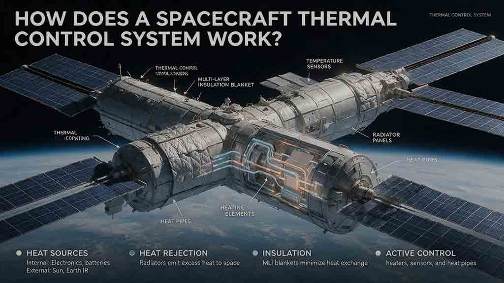
A spacecraft thermal control system keeps onboard equipment within safe operating and survival temperatures by controlling how heat is absorbed, generated, transported, stored, and released. This guide explains how passive technologies—including multilayer insulation, thermal coatings, heat pipes, straps, and radiators—work alongside active systems such as heaters, temperature sensors, cryocoolers, and pumped fluid loops. It introduces the original Protect–Move–Reject–Trim–Verify framework for understanding complete spacecraft heat paths and provides practical tools for evaluating thermal designs. Readers will also find a worked radiator-sizing example, a thermal-resistance calculation, mission-specific selection guidance, common design mistakes, troubleshooting methods, and real examples from the James Webb Space Telescope, International Space Station, and Europa Clipper. Based on publicly available NASA and ESA documentation, the article distinguishes simplified educational calculations from actual flight-design analysis while showing why spacecraft must be protected from both overheating and excessive cooling.
How Do Spacecraft Communicate With Earth?
Spacecraft communicate with Earth by sending encoded information through radio waves or laser light. This guide explains the complete path from an onboard instrument and computer to a transmitter, antenna, ground station, and mission-control center. It covers uplinks, downlinks, telemetry, tracking, direct-to-Earth communication, relay satellites, spacecraft crosslinks, and onboard data storage. Readers will also learn why signals weaken over distance, how communication delays are calculated, and how antenna gain, transmitter power, data rate, coding, pointing accuracy, and ground-network availability affect link reliability. Worked examples show how long a signal may take to travel between Mars and Earth and how much data can be returned during a scheduled contact. Real mission examples—including NASA’s Deep Space Network, the Mars Relay Network, the James Webb Space Telescope, and the DSOC optical demonstration—show how these engineering principles are applied in practice.
How Do Spacecraft Control Their Direction in Space?
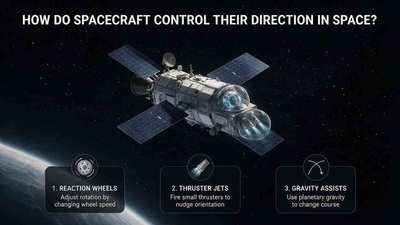
Spacecraft control their direction through a coordinated attitude determination and control system. Sensors such as star trackers, Sun sensors, magnetometers, and gyroscopes estimate the spacecraft’s orientation, while onboard software compares that estimate with the required pointing direction. Reaction wheels, thrusters, control moment gyroscopes, and magnetic torquers then apply the necessary control torque. Some missions also use spin stabilization to resist unwanted changes in orientation. This article explains the difference between attitude and trajectory, follows the Sense → Estimate → Compare → Act → Verify control loop, and compares the strengths and limitations of major control methods. It also includes simplified torque and momentum calculations, real spacecraft examples from NASA and ESA missions, troubleshooting scenarios, and a practical framework for evaluating attitude-control architectures. Readers will learn why spacecraft pointing depends on an integrated system rather than a single steering device.
Explore More Topics
How Do Spacecraft Return Safely Through Earth’s Atmosphere?
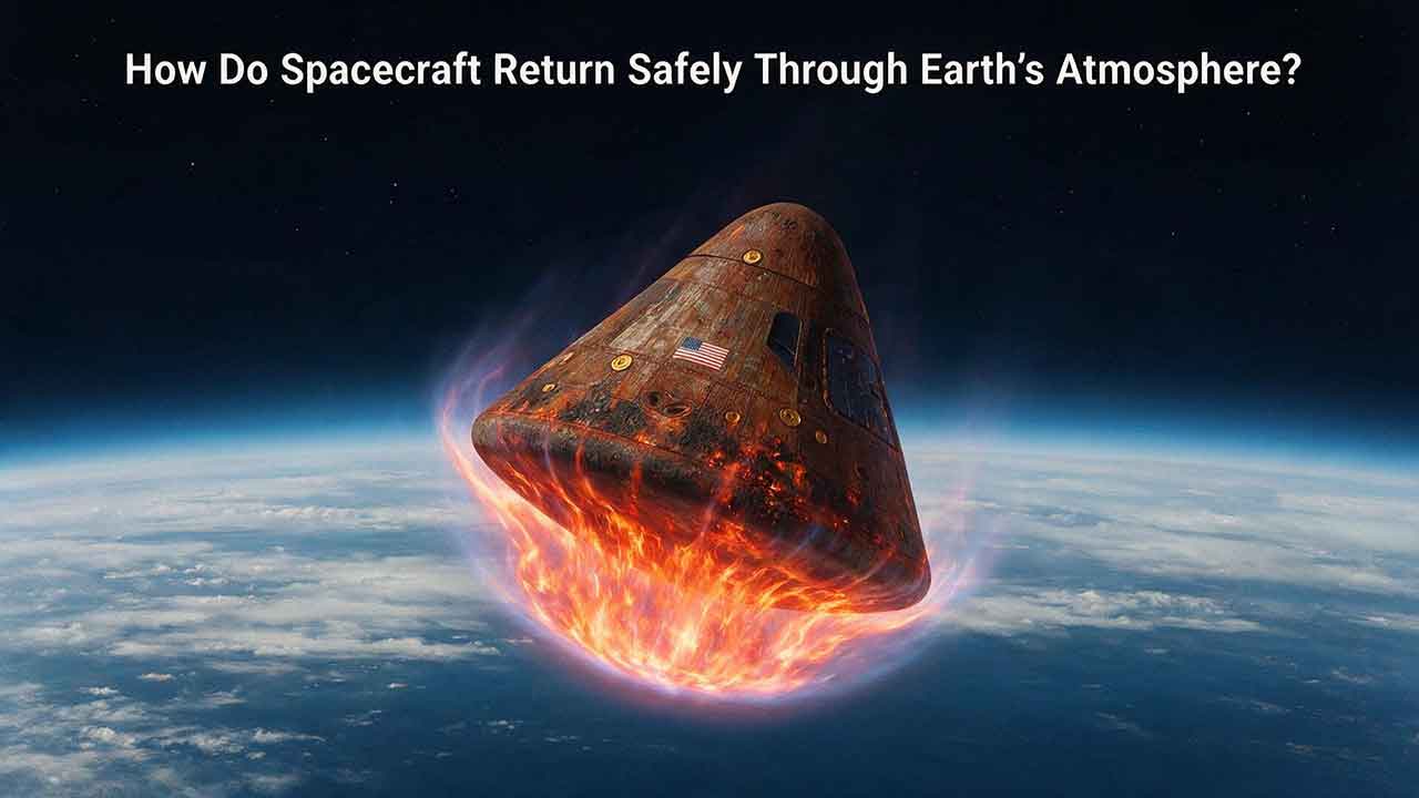
Spacecraft return safely through Earth’s atmosphere by managing an enormous amount of energy through a carefully coordinated sequence of trajectory control, thermal protection, aerodynamic deceleration, landing, and recovery. This article explains how deorbit burns and entry corridors guide a spacecraft toward its landing region, why blunt heat shields reduce the danger of hypersonic heating, and how guidance systems control attitude, range, and structural loads. It includes an original comparison of low-Earth-orbit and lunar-return energy, a practical review of ablative and reusable heat-shield technologies, and the CosmoBasics Four-Layer Reentry Framework covering path, protection, control, descent, and recovery. Real-world lessons from Artemis I and the crewed Artemis II mission show why postflight inspection remains essential even after a successful splashdown. Readers will also learn how parachutes, wings, landing rockets, flotation systems, and recovery teams complete the return safely.

How Do Astronauts Sleep, Eat, and Exercise in Space?
Astronauts must redesign ordinary routines when they live in microgravity. This article explains how crew members sleep in secured bags inside ventilated quarters, prepare packaged meals without letting food or liquids drift through the cabin, and use specialized exercise equipment to protect their physical condition. It examines the roles of the Advanced Resistive Exercise Device, the T2 treadmill, and the CEVIS cycle ergometer, while clarifying the difference between active workout time and the full scheduled exercise period. Readers will also learn why tortillas are practical in space, how airflow affects sleep, why ordinary weights do not work normally in orbit, and how nutrition, rest, and exercise support one another. NASA and ESA sources provide the factual foundation, while original comparison tables and practical evaluation frameworks show how spacecraft systems replace functions normally supplied by gravity. The article also distinguishes current International Space Station practices from possible future Moon and Mars mission requirements.
What Happens to the Human Body in Microgravity?
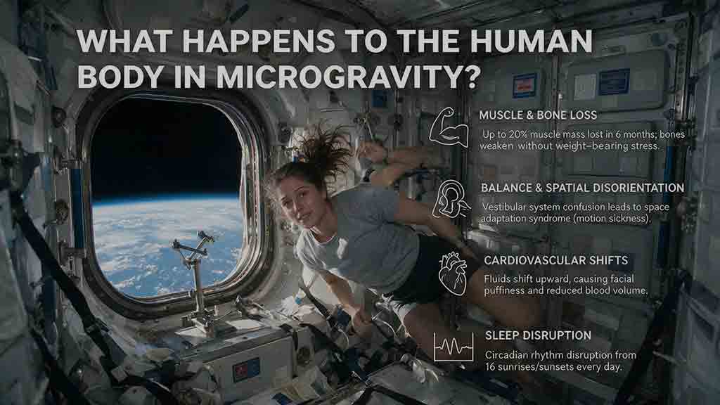
Microgravity changes the human body because fluids are no longer pulled toward the legs, muscles and bones receive less mechanical loading, and the brain loses gravity as a dependable orientation signal. This article explains how weightlessness affects balance, circulation, muscle strength, bone density, vision, blood, immunity, digestion, sleep, and spinal length. It also examines why astronauts may struggle to stand or walk after landing and how exercise, nutrition, monitoring, and rehabilitation help reduce these risks. Two original tools—the Load–Flow–Orientation Framework and the Gravity-Transition Readiness Matrix—connect physiological changes with real mission demands. Drawing on NASA standards, NASA technical reports, ESA materials, and peer-reviewed human spaceflight research, the guide clearly separates established observations from experimental countermeasures and unresolved questions. It also explains what these effects could mean for future missions to the Moon and Mars without treating population averages as predictions for individual astronauts.